Wiring the Transmitter to the Sensor
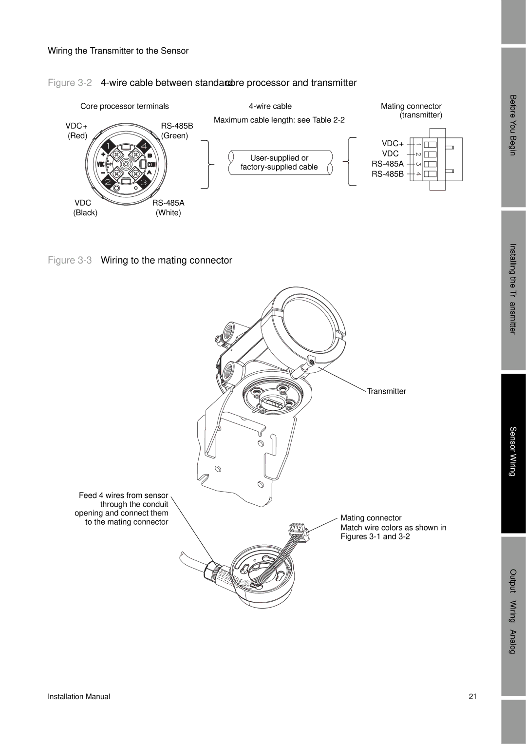
Figure 3-2 4-wire cable between standard core processor and transmitter
Core processor terminals |
Maximum cable length: see Table
VDC+ | |
(Red) | (Green) |
VDC– ![]() RS-485A
RS-485A
(Black)(White)
Mating connector (transmitter)
VDC+ ![]()
![]()
![]() VDC–
VDC– ![]()
![]()
![]()
![]()
![]()
![]()
![]()
![]()
![]()
![]()
![]()
Before You Begin
Figure 3-3 Wiring to the mating connector
Transmitter
Feed 4 wires from sensor |
| |
through the conduit |
| |
opening and connect them | Mating connector | |
to the mating connector | ||
Match wire colors as shown in | ||
| ||
| Figures |
Installing the Transmitter
Sensor Wiring
Output Wiring – Analog
Installation Manual | 21 |