Output Wiring – Model 1700/2700 Intrinsically Safe Transmitters
5.4.2Hazardous area mA output wiring
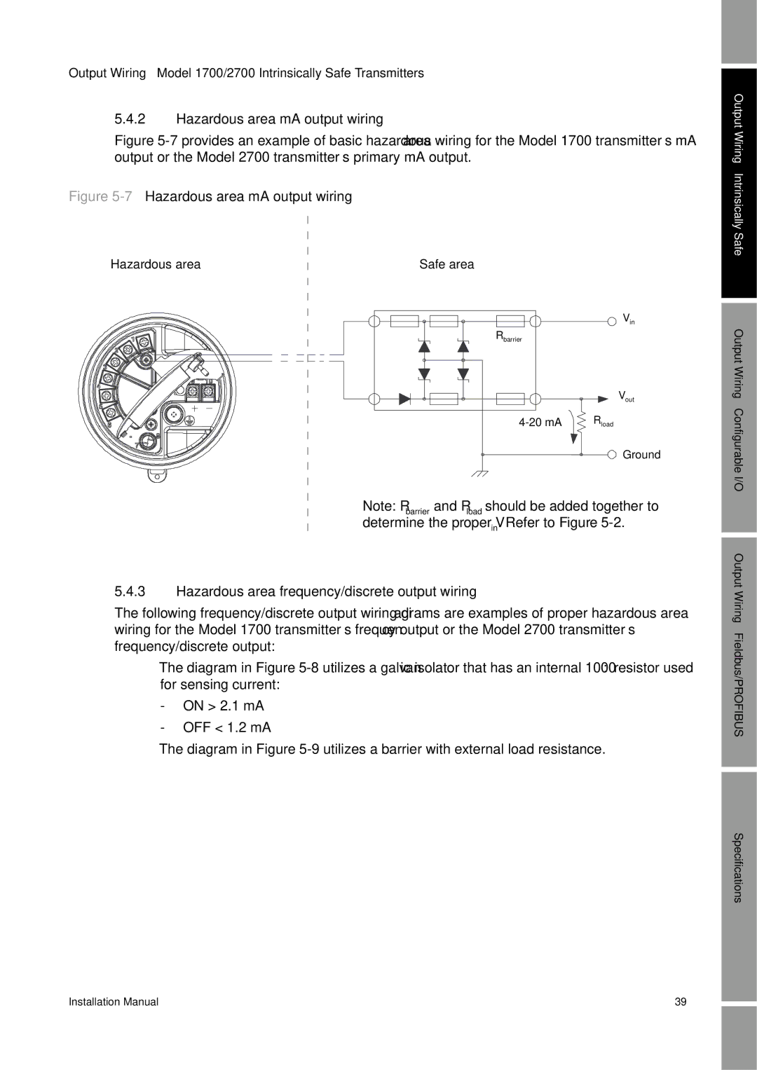
Figure 5-7 provides an example of basic hazardous area wiring for the Model 1700 transmitter’s mA output or the Model 2700 transmitter’s primary mA output.
Figure 5-7 Hazardous area mA output wiring
Output Wiring – Intrinsically
Hazardous area
Safe area |
|
| Vin |
Rbarrier |
|
| Vout |
Rload | |
| Ground |
Note: Rbarrier and Rload should be added together to determine the proper Vin. Refer to Figure
Safe
Output Wiring – Configurable I/O Output
5.4.3Hazardous area frequency/discrete output wiring
The following frequency/discrete output wiring diagrams are examples of proper hazardous area wiring for the Model 1700 transmitter’s frequency output or the Model 2700 transmitter’s frequency/discrete output:
•The diagram in Figure
-ON > 2.1 mA
-OFF < 1.2 mA
•The diagram in Figure
Wiring – Fieldbus/PROFIBUS
Specifications
Installation Manual | 39 |