Emerson 1700, 2700 installation manual wirecable, 3.3Wiring for 4-wireremote installations

Models: 2700 1700

1 80
Download 80 pages 1.45 Kb
Page 24
Image 24
3.2.14-wire cable

Wiring the Transmitter to the Sensor

3.2.14-wire cable

Micro Motion offers two types of 4-wire cable: shielded and armored. Both types contain shield drain wires.

User-supplied 4-wire cable must meet the following requirements:

Twisted pair construction

The gauge requirements as described in Table 2-2

The applicable hazardous area requirements, if the core processor is installed in a hazardous area (see the approval documentation shipped with the transmitter or available on the Micro Motion web site)

3.2.29-wire cable

Micro Motion offers three types of 9-wire cable: jacketed, shielded, and armored. Refer to Micro Motion’s 9-Wire Flowmeter Cable Preparation and Installation Guide for detailed descriptions of these cable types and for assistance in selecting the appropriate cable for your installation.

3.3Wiring for 4-wire remote installations

To connect the cable, follow the steps below.

1.Prepare the cable as described in the sensor documentation.

2.Connect the cable to the core processor as described in the sensor documentation.

3.To connect the cable to the transmitter:

a.Identify the wires in the 4-wire cable. The 4-wire cable supplied by Micro Motion consists of one pair of 18 AWG (0,75 mm2) wires (red and black), which should be used for the VDC connection, and one pair of 22 AWG (0,35 mm2) wires (green and white), which should be used for the RS-485 connection.

b.Connect the four wires from the core processor to terminals
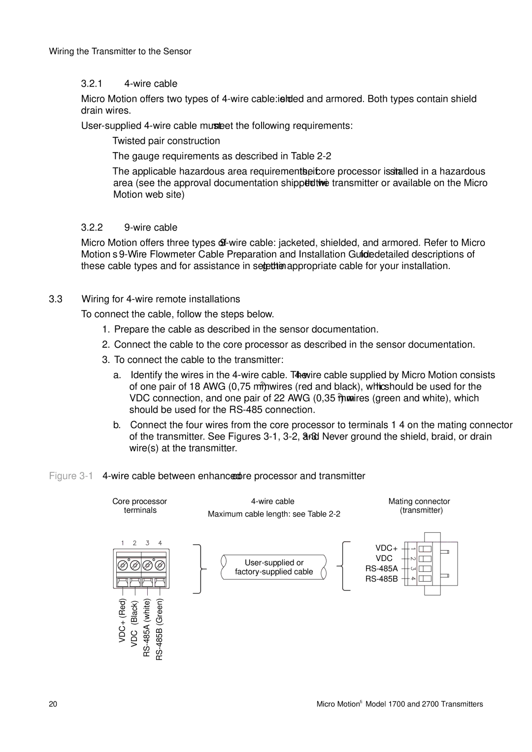
 1–4 on the mating connector of the transmitter. See Figures 3-1,3-2,and 3-3.Never ground the shield, braid, or drain wire(s) at the transmitter.

Figure 3-14-wire cable between enhanced core processor and transmitter

Core processor

4-wire cable

terminals

Maximum cable length: see Table 2-2


User-supplied or

factory-supplied cable

VDC+ (Red)

VDC– (Black)

RS-485A (white)

RS-485B (Green)

Mating connector (transmitter)

VDC+ 3.2.29-wire cable3.3Wiring for 4-wire remote installationsManual backgroundManual backgroundManual background

VDC– Manual backgroundManual backgroundManual background

RS-485A Manual backgroundManual backgroundManual backgroundManual backgroundManual background

RS-485B Manual backgroundManual backgroundManual background

20

Micro Motion® Model 1700 and 2700 Transmitters

Page 24
Image 24
Emerson 1700, 2700 installation manual wirecable, 3.3Wiring for 4-wireremote installations