Output Wiring – Model 2700 FOUNDATION FIELDBUS and
7.3PROFIBUS-PA wiring
Wire the transmitter to the
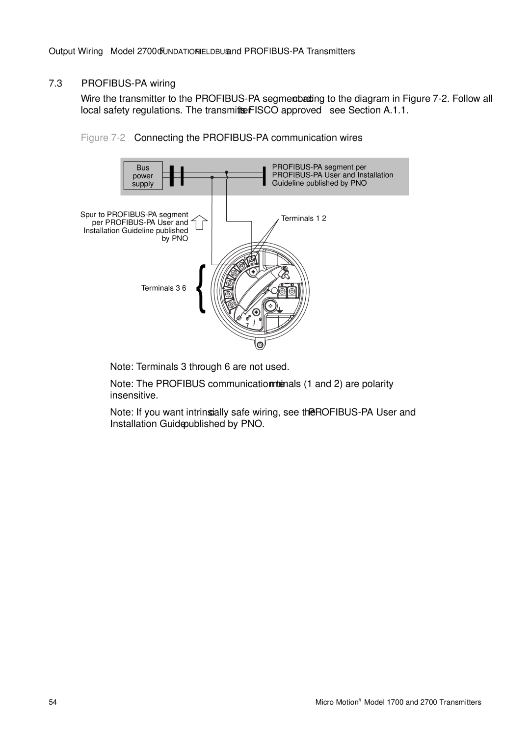
Figure 7-2 Connecting the PROFIBUS-PA communication wires
Bus
power supply
Spur to |
|
|
| Terminals |
per |
|
|
| |
|
|
|
| |
Installation Guideline published |
|
|
|
|
|
|
|
| |
by PNO |
|
|
|
|
Terminals
Note: Terminals 3 through 6 are not used.
Note: The PROFIBUS communication terminals (1 and 2) are polarity insensitive.
Note: If you want intrinsically safe wiring, see the
54 | Micro Motion® Model 1700 and 2700 Transmitters |