Output Wiring – Model 1700/2700 Intrinsically Safe Transmitters
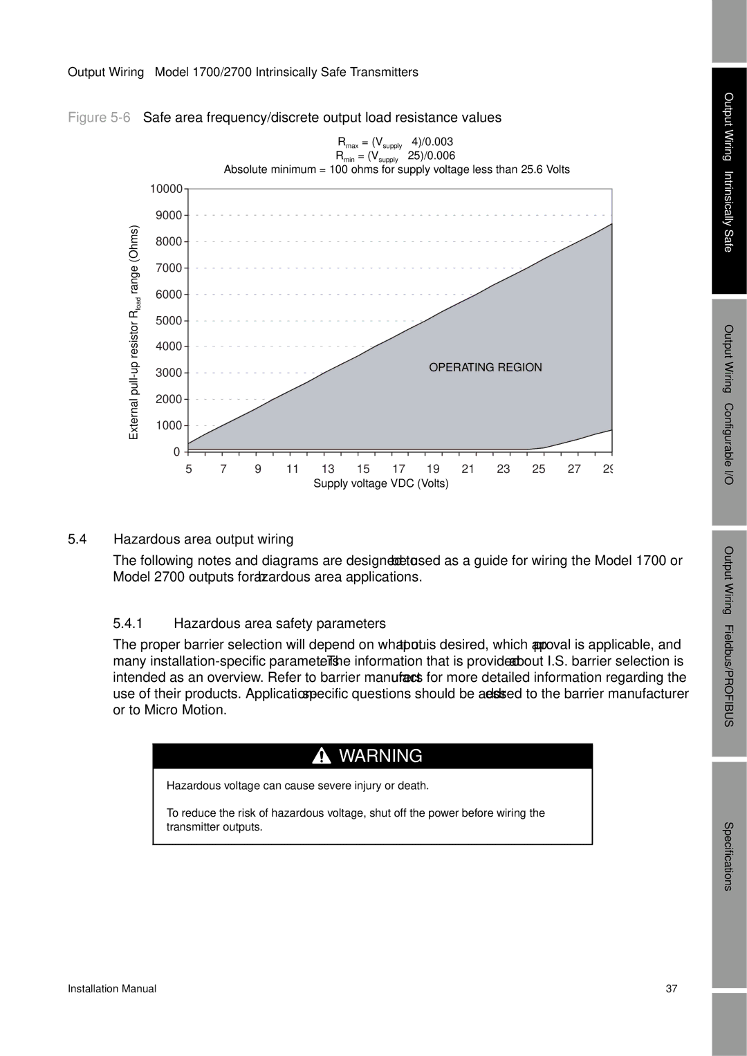
Figure 5-6 Safe area frequency/discrete output load resistance values
Rmax = (Vsupply – 4)/0.003
Rmin = (Vsupply – 25)/0.006
Absolute minimum = 100 ohms for supply voltage less than 25.6 Volts
| 10000 |
|
|
|
|
|
|
|
|
|
|
|
|
| 9000 |
|
|
|
|
|
|
|
|
|
|
|
|
(Ohms) | 8000 |
|
|
|
|
|
|
|
|
|
|
|
|
7000 |
|
|
|
|
|
|
|
|
|
|
|
| |
range |
|
|
|
|
|
|
|
|
|
|
|
| |
6000 |
|
|
|
|
|
|
|
|
|
|
|
| |
load |
|
|
|
|
|
|
|
|
|
|
|
| |
|
|
|
|
|
|
|
|
|
|
|
|
| |
R | 5000 |
|
|
|
|
|
|
|
|
|
|
|
|
|
|
|
|
|
|
|
|
|
|
|
| ||
4000 |
|
|
|
|
|
|
|
|
|
|
|
| |
3000 |
|
|
|
|
|
| OPERATING REGION |
|
| ||||
pull | 2000 |
|
|
|
|
|
|
|
|
|
|
|
|
External |
|
|
|
|
|
|
|
|
|
|
|
| |
1000 |
|
|
|
|
|
|
|
|
|
|
|
| |
|
|
|
|
|
|
|
|
|
|
|
|
| |
| 0 |
|
|
|
|
|
|
|
|
|
|
|
|
| 5 | 7 | 9 | 11 | 13 | 15 | 17 | 19 | 21 | 23 | 25 | 27 | 29 |
Supply voltage VDC (Volts)
5.4Hazardous area output wiring
The following notes and diagrams are designed to be used as a guide for wiring the Model 1700 or Model 2700 outputs for hazardous area applications.
5.4.1Hazardous area safety parameters
The proper barrier selection will depend on what output is desired, which approval is applicable, and many
![]()
![]()
![]() WARNING
WARNING
Hazardous voltage can cause severe injury or death.
To reduce the risk of hazardous voltage, shut off the power before wiring the transmitter outputs.
Output Wiring – Intrinsically Safe
Output Wiring – Configurable I/O Output Wiring – Fieldbus/PROFIBUS
Specifications
Installation Manual | 37 |