Output Wiring – Model 2700 Configurable I/O Transmitters
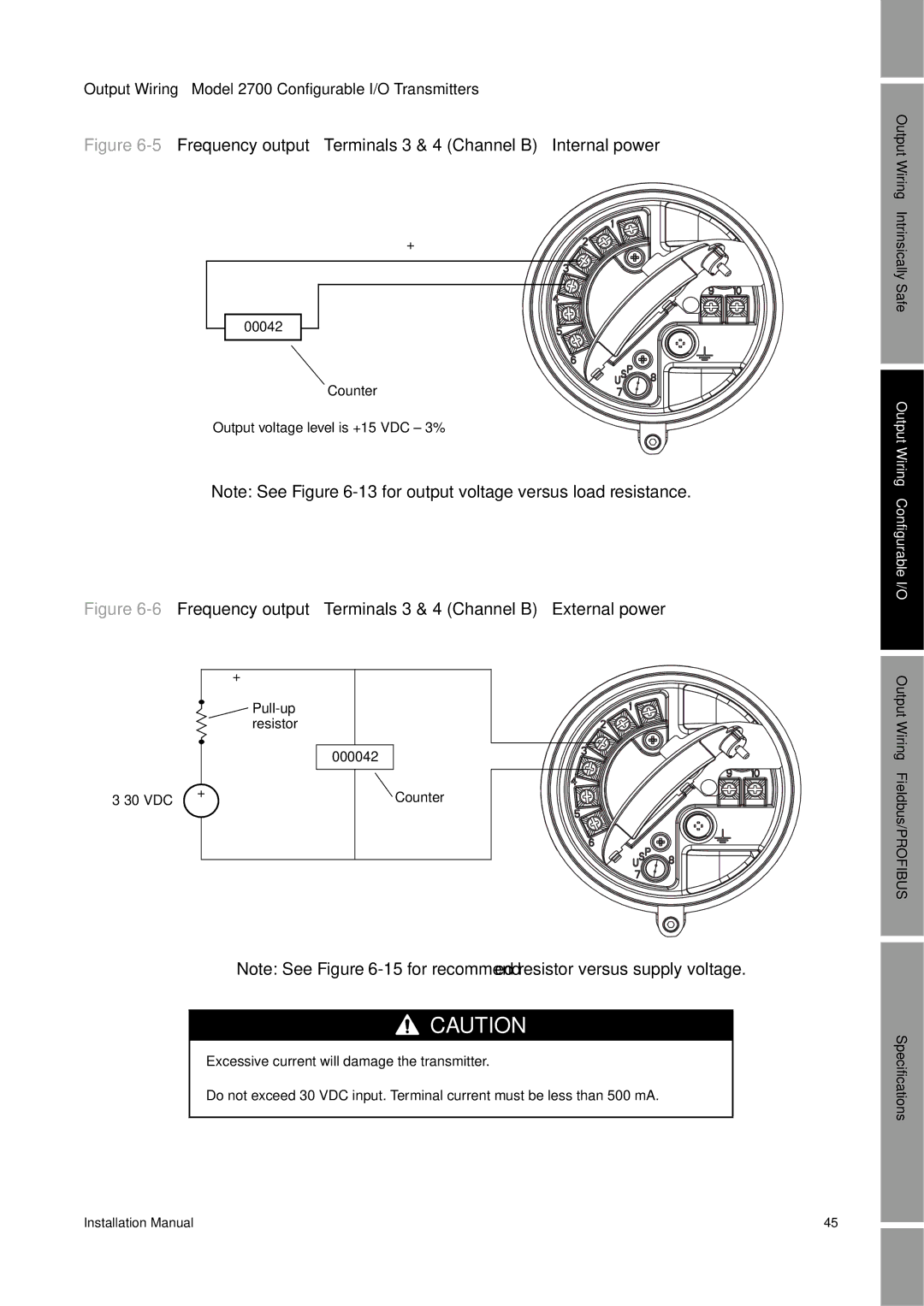
Figure 6-5 Frequency output – Terminals 3 & 4 (Channel B) – Internal power
+
–
00042 |
Counter
Output voltage level is +15 VDC ± 3%
Note: See Figure
Figure 6-6 Frequency output – Terminals 3 & 4 (Channel B) – External power
|
| + | |
|
| ||
|
| resistor | |
|
| 000042 | |
+ | Counter | ||
– | |||
|
| ||
|
| – |
Note: See Figure
![]()
![]()
![]() CAUTION
CAUTION
Excessive current will damage the transmitter.
Do not exceed 30 VDC input. Terminal current must be less than 500 mA.
Output Wiring – Intrinsically Safe
Output Wiring – Configurable I/O Output Wiring – Fieldbus/PROFIBUS
Specifications
Installation Manual | 45 |