Output Wiring – Model 1700/2700 Intrinsically Safe Transmitters
5.3Safe area output wiring
The following notes and diagrams are designed to be used as a guide for wiring the Model 1700 or Model 2700 outputs for safe area applications.
5.3.1Safe area mA output wiring
The following
Note: This diagram shows the Model 2700, which has a secondary mA output. If you are using the Model 1700, the secondary mA output does not exist.
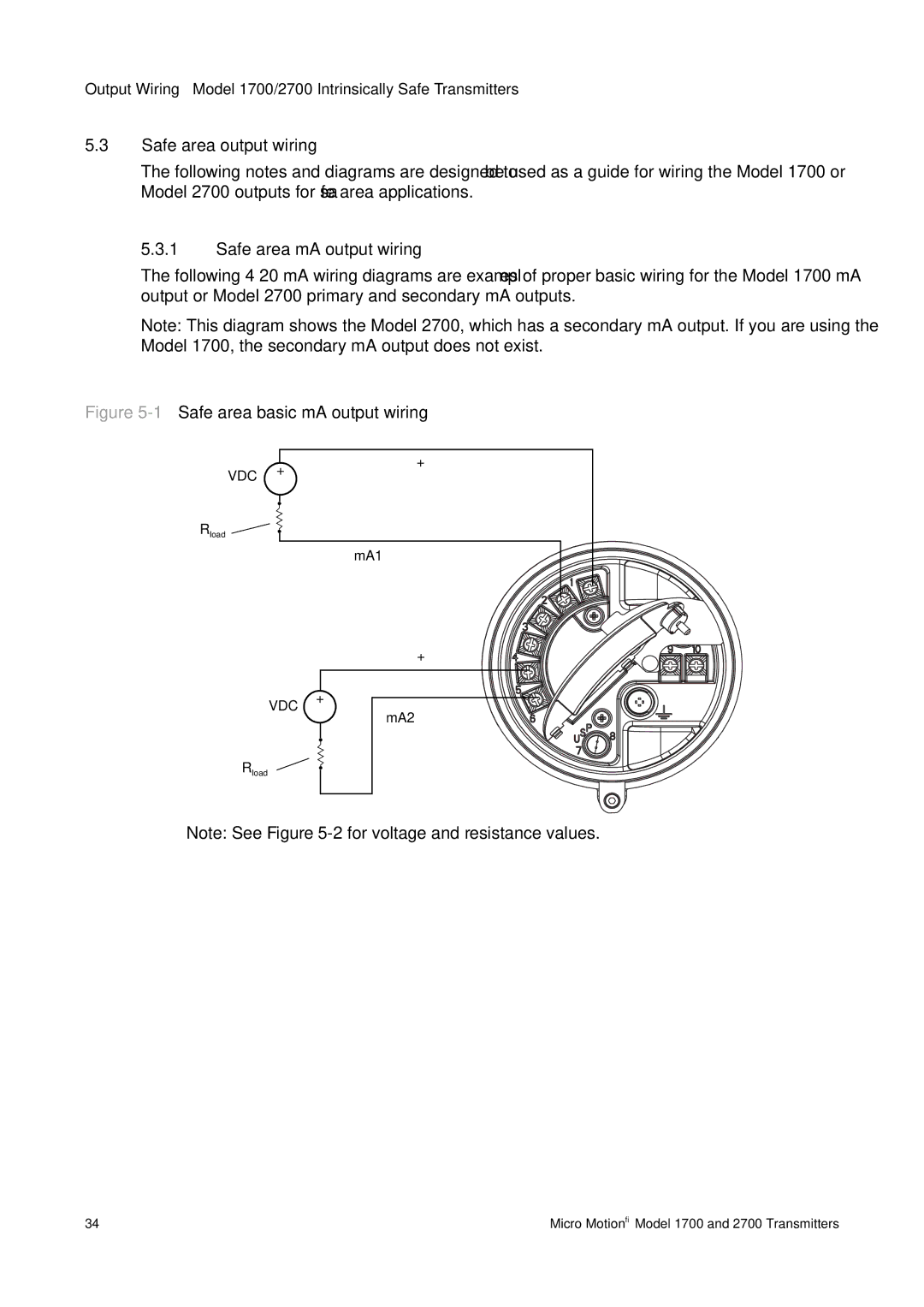
Figure 5-1 Safe area basic mA output wiring
| VDC | + | + |
|
| ||
| – |
| |
|
|
| |
Rload |
|
| – |
|
|
| mA1 |
|
| + | |
VDC | + | – | |
| |||
– | mA2 | ||
| |||
|
|
Rload
Note: See Figure
34 | Micro Motion® Model 1700 and 2700 Transmitters |