Installing the Transmitter
2.7Supplying power
In all installations, power must be provided to the transmitter. Refer to Section 2.3.3 for information on the transmitter’s power supply requirements.
A
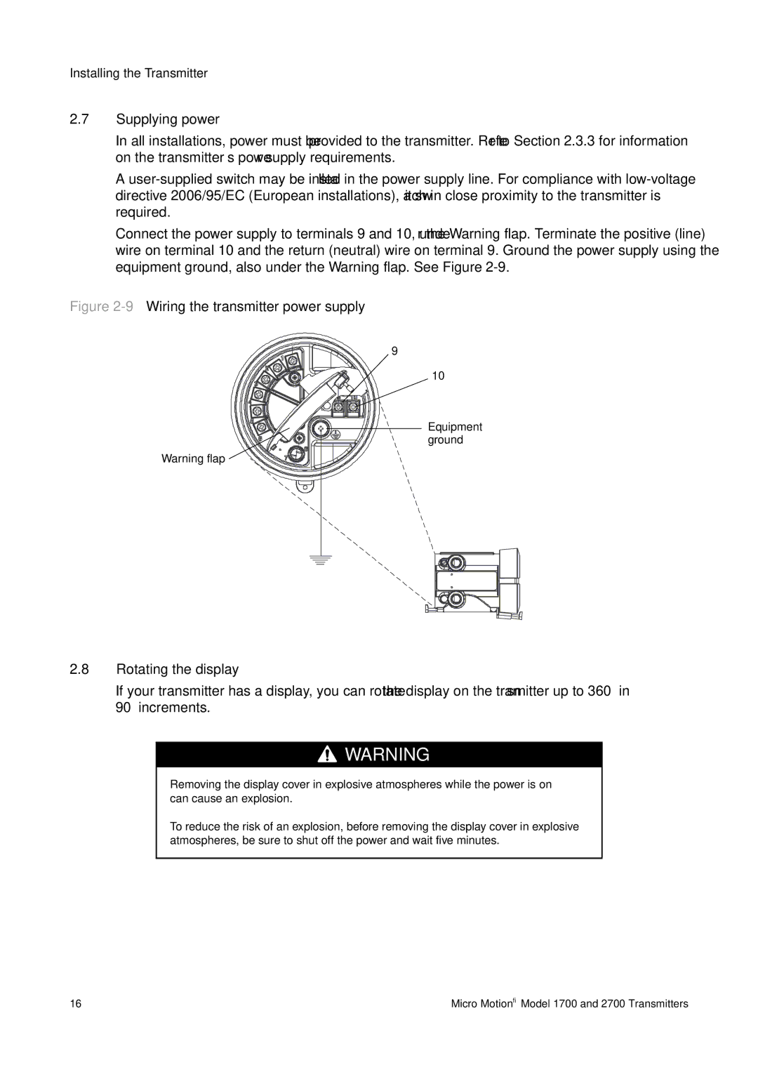
Connect the power supply to terminals 9 and 10, under the Warning flap. Terminate the positive (line) wire on terminal 10 and the return (neutral) wire on terminal 9. Ground the power supply using the equipment ground, also under the Warning flap. See Figure
Figure 2-9 Wiring the transmitter power supply
Warning flap
9
10
Equipment ground
2.8Rotating the display
If your transmitter has a display, you can rotate the display on the transmitter up to 360° in 90° increments.
![]()
![]()
![]() WARNING
WARNING
Removing the display cover in explosive atmospheres while the power is on can cause an explosion.
To reduce the risk of an explosion, before removing the display cover in explosive atmospheres, be sure to shut off the power and wait five minutes.
16 | Micro Motion® Model 1700 and 2700 Transmitters |