Wiring the Transmitter to the Sensor
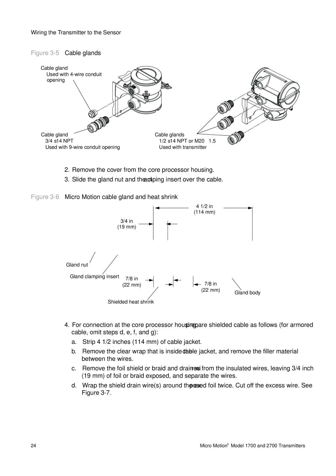
Figure 3-5 Cable glands
Cable gland
• Used with
Cable gland |
| Cable glands | ||
• | • | |||
• | Used with | • | Used with transmitter | |
2.Remove the cover from the core processor housing.
3.Slide the gland nut and the clamping insert over the cable.
Figure 3-6 Micro Motion cable gland and heat shrink
3/4 in
(19 mm)
Gland nut
Gland clamping insert | 7/8 in |
|
|
|
| ||
| (22 mm) | ||
Shielded heat shrink | |||
4 1/2 in
(114 mm)
7/8 in |
|
(22 mm) | Gland body |
|
4.For connection at the core processor housing, prepare shielded cable as follows (for armored cable, omit steps d, e, f, and g):
a.Strip 4 1/2 inches (114 mm) of cable jacket.
b.Remove the clear wrap that is inside the cable jacket, and remove the filler material between the wires.
c.Remove the foil shield or braid and drain wires from the insulated wires, leaving 3/4 inch (19 mm) of foil or braid exposed, and separate the wires.
d.Wrap the shield drain wire(s) around the exposed foil twice. Cut off the excess wire. See Figure
24 | Micro Motion® Model 1700 and 2700 Transmitters |