Wiring the Transmitter to the Sensor
8.At the transmitter, connect the four wires from the core processor to terminals
Subtask 2: Wiring the sensor to the remote core processor
![]()
![]()
![]() CAUTION
CAUTION
Allowing the shield drain wires to contact the sensor junction box can cause flowmeter errors.
Do not allow the shield drain wires to contact the sensor junction box.
1.Refer to Micro Motion’s
•At the sensor end, follow the instructions for your cable type.
•At the core processor end, follow the instructions for your cable type with an MVD transmitter.
2.To connect the wires, refer to Micro Motion’s
a.Identify the components shown in Figure
b.Remove the
c.Insert the
d.Connect the wires to the plugs supplied with the core processor.
e.Insert the plugs into the sockets inside the lower conduit ring. See Figure
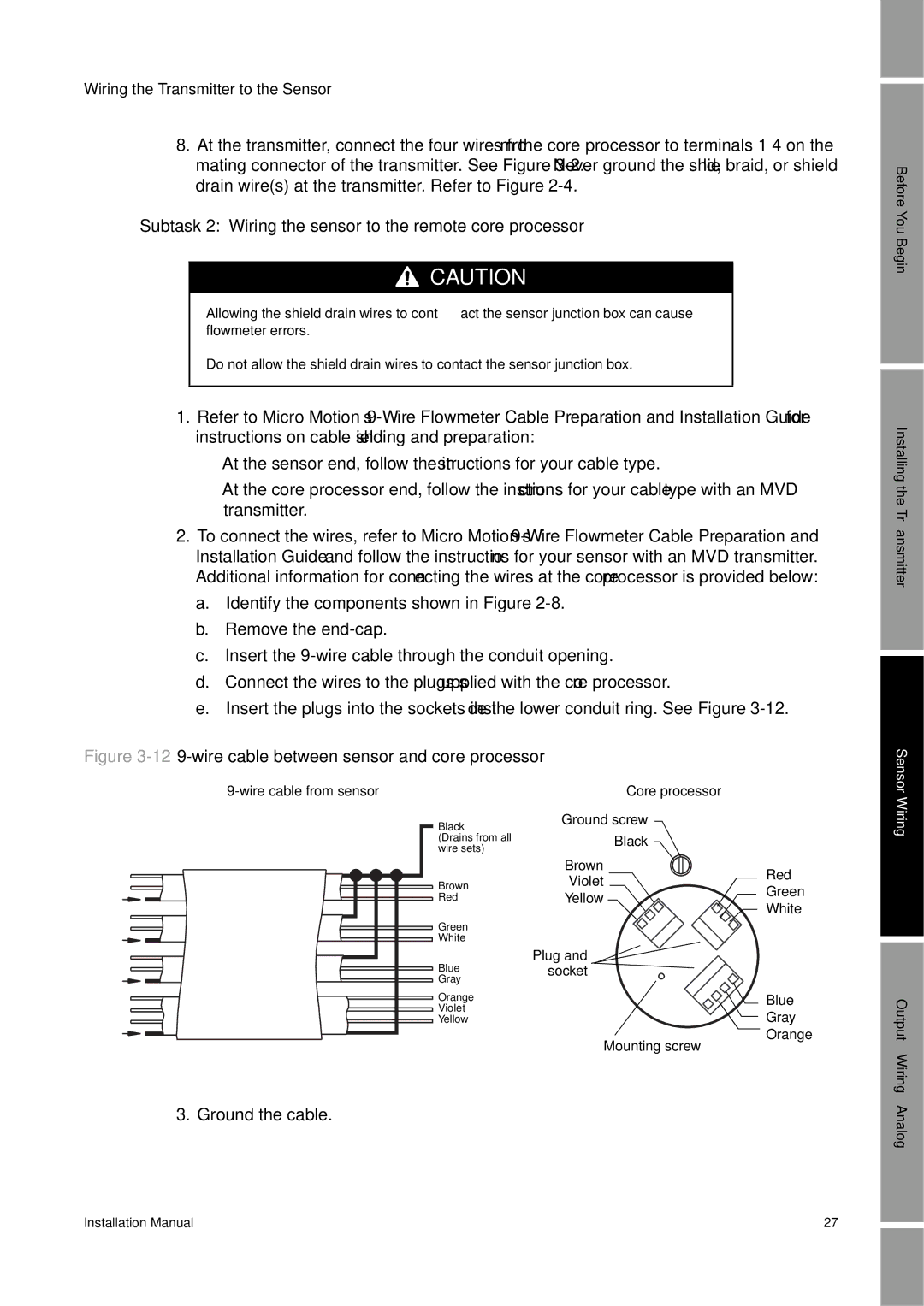
Figure 3-12 9-wire cable between sensor and core processor
Core processor |
Black | Ground screw |
| |
(Drains from all | Black |
| |
wire sets) |
|
| |
| Brown | Red | |
Brown | Violet | ||
Green | |||
Red | Yellow | ||
White | |||
|
| ||
Green |
|
| |
White |
|
| |
Blue | Plug and |
| |
socket |
| ||
Gray |
|
| |
Orange |
| Blue | |
Violet |
| Gray | |
Yellow |
| ||
| Mounting screw | Orange | |
|
|
3. Ground the cable.
Before You Begin
Installing the Transmitter
Sensor Wiring
Output Wiring – Analog
Installation Manual | 27 |