Wiring the Transmitter to the Sensor
3.4Wiring for 9-wire remote installations
If you chose a
![]()
![]()
![]() CAUTION
CAUTION
Allowing the shield drain wires to contact the sensor junction box can cause flowmeter errors.
Do not allow the shield drain wires to contact the sensor junction box.
To connect the cable, follow the steps below:
1.Refer to Micro Motion’s
•At the sensor end, follow the instructions for your cable type.
•At the transmitter end, follow the instructions for your cable type with an MVD transmitter.
2.To connect the wires, refer to Micro Motion’s
a.Identify the components shown in Figure
b.Remove the
c.Insert the
d.Connect the wires to the plugs supplied with the transmitter.
e.Insert the plugs into the sockets inside the lower conduit ring. See Figure
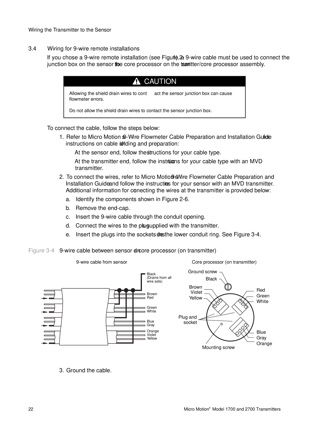
Figure 3-4 9-wire cable between sensor and core processor (on transmitter)
Black
(Drains from all wire sets)
Core processor (on transmitter)
Ground screw
Black
Brown |
Red |
Green |
White |
Blue |
Gray |
Orange |
Violet |
Yellow |
Brown | Red | |
Violet | ||
Green | ||
Yellow | ||
White | ||
|
Plug and ![]() socket
socket
Blue
Gray
Orange
Mounting screw
3. Ground the cable.
22 | Micro Motion® Model 1700 and 2700 Transmitters |