Rosemount 3051N
Reference Manual
Smart transmitters operate differently than analog transmitters. A smart transmitter uses a microprocessor and sensor memory that contains information about the sensor’s specific characteristics in response to pressure and temperature inputs. A smart transmitter compensates for these sensor variations. The process of generating the sensor performance profile is called factory characterization. Factory characterization also provides the ability to readjust the 4 and 20 mA points without applying pressure to the transmitter.
The trim and rerange functions also differ. Reranging sets the transmitter analog output to the selected upper and lower range points and can be done with or without an applied pressure. Reranging does not change the factory characterization curve stored in the microprocessor. Sensor trimming requires an accurate pressure input and adds additional compensation that adjusts the position of the factory characterization curve to optimize transmitter performance over a specific pressure range.
NOTE
Sensor trimming adjusts the position of the factory characterization curve. It is possible to degrade the performance of the transmitter if the sensor trim is done improperly or with inaccurate equipment. Contact Rosemount Nuclear Instruments, Inc. at
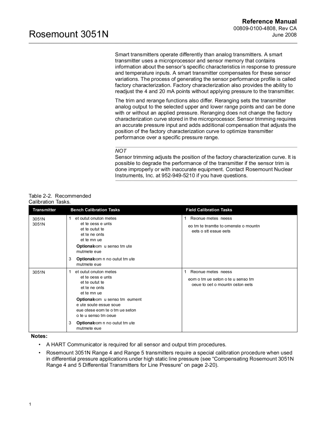
Table
Calibration Tasks.
Transmitter | Bench Calibration Tasks | Field Calibration Tasks | ||
|
|
|
|
|
3051ND | 1. | Set output configuration parameters: | 1. | Reconfigure parameters if necessary. |
3051NG |
| a. Set the process variable units. | 2. Zero trim the transmitter to compensate for mounting | |
|
| b. Set the output type. | ||
|
|
| effects or static pressure effects. | |
|
| c. Set the range points. |
| |
|
|
|
| |
|
| d. Set the damping value. |
|
|
| 2. | Optional: Perform a full sensor trim. (Accurate |
|
|
|
| multimeter required.) |
|
|
| 3. | Optional: Perform an analog output trim. (Accurate |
|
|
|
| multimeter required.) |
|
|
|
|
|
|
|
3051NA | 1. | Set output configuration parameters: | 1. | Reconfigure parameters if necessary. |
|
| a. Set the process variable units. | 2. | Perform low trim value section of the full sensor trim |
|
| b. Set the output type. | ||
|
|
| procedure to correct for mounting position effects. | |
|
| c. Set the range points. |
| |
|
|
|
| |
|
| d. Set the damping value. |
|
|
| 2. | Optional: Perform a full sensor trim if equipment |
|
|
|
| available (accurate absolute pressure source |
|
|
|
| required), otherwise perform the low trim value section |
|
|
|
| of the full sensor trim procedure. |
|
|
| 3. | Optional: Perform an analog output trim (accurate |
|
|
|
| multimeter required). |
|
|
|
|
|
|
|
Notes:
•A HART Communicator is required for all sensor and output trim procedures.
•Rosemount 3051N Range 4 and Range 5 transmitters require a special calibration procedure when used in differential pressure applications under high static line pressure (see “Compensating Rosemount 3051N Range 4 and 5 Differential Transmitters for Line Pressure” on page
