Reference Manual
Rosemount 3051N
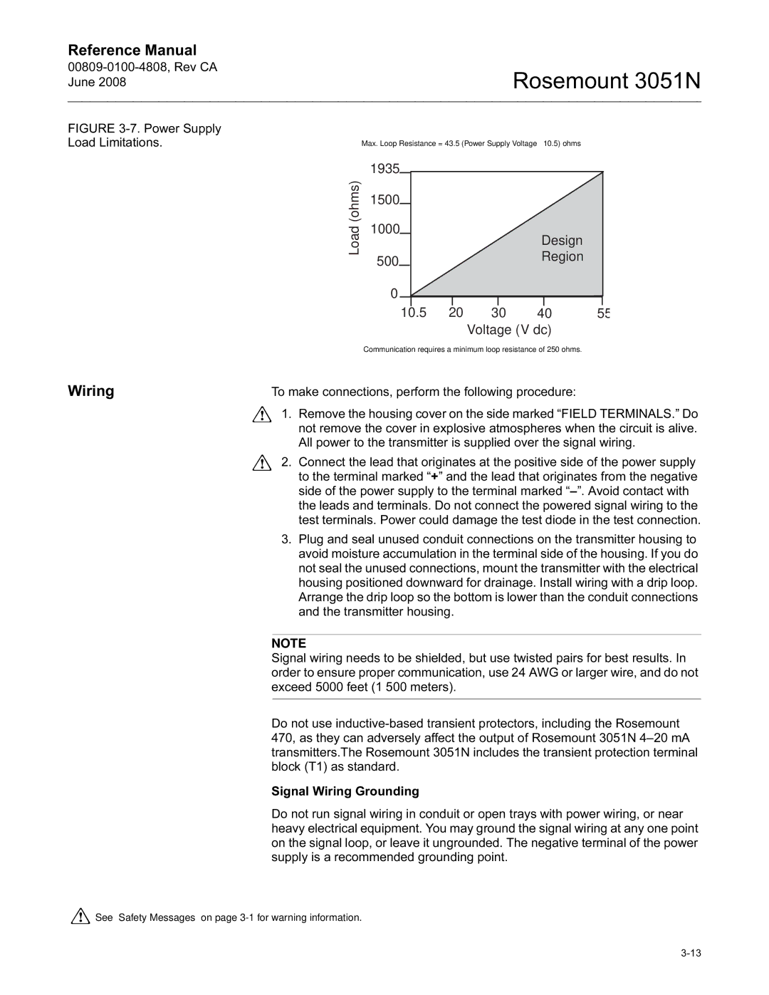
FIGURE 3-7. Power Supply Load Limitations.
Max. Loop Resistance = 43.5 (Power Supply Voltage – 10.5) ohms
Load (ohms)
1935 |
|
|
|
|
|
|
1500 |
|
|
|
|
|
|
|
|
|
|
|
| |
1000 |
|
|
|
| Design | |
|
|
|
|
| ||
500 |
|
|
|
| Region | |
0 |
|
|
|
|
|
|
|
|
|
|
|
|
|
10.5 | 20 | 30 | 40 | 55 |
|
| Voltage (V dc) |
| |
| Communication requires a minimum loop resistance of 250 ohms. |
Wiring | To make connections, perform the following procedure: |
| 1. Remove the housing cover on the side marked “FIELD TERMINALS.” Do |
| not remove the cover in explosive atmospheres when the circuit is alive. |
| All power to the transmitter is supplied over the signal wiring. |
| 2. Connect the lead that originates at the positive side of the power supply |
| to the terminal marked “+” and the lead that originates from the negative |
| side of the power supply to the terminal marked |
| the leads and terminals. Do not connect the powered signal wiring to the |
| test terminals. Power could damage the test diode in the test connection. |
| 3. Plug and seal unused conduit connections on the transmitter housing to |
| avoid moisture accumulation in the terminal side of the housing. If you do |
| not seal the unused connections, mount the transmitter with the electrical |
| housing positioned downward for drainage. Install wiring with a drip loop. |
| Arrange the drip loop so the bottom is lower than the conduit connections |
| and the transmitter housing. |
|
|
| NOTE |
| Signal wiring needs to be shielded, but use twisted pairs for best results. In |
| order to ensure proper communication, use 24 AWG or larger wire, and do not |
| exceed 5000 feet (1 500 meters). |
|
|
| Do not use |
| 470, as they can adversely affect the output of Rosemount 3051N |
| transmitters.The Rosemount 3051N includes the transient protection terminal |
| block (T1) as standard. |
| Signal Wiring Grounding |
| Do not run signal wiring in conduit or open trays with power wiring, or near |
| heavy electrical equipment. You may ground the signal wiring at any one point |
| on the signal loop, or leave it ungrounded. The negative terminal of the power |
| supply is a recommended grounding point. |
![]() See “Safety Messages” on page
See “Safety Messages” on page