Operator Control Panel and Display

Table 23

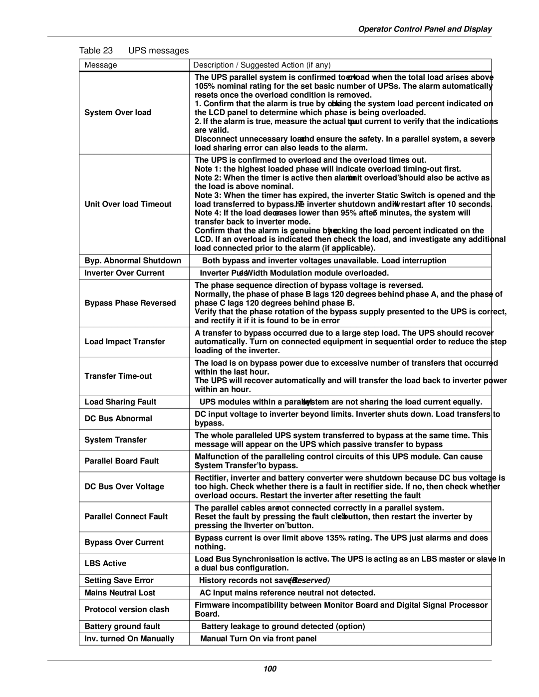
UPS messages


Message


Description / Suggested Action (if any)


The UPS parallel system is confirmed to overload when the total load arises above


105% nominal rating for the set basic number of UPSs. The alarm automatically


resets once the overload condition is removed.


1. Confirm that the alarm is true by checking the system load percent indicated on

System Over load


the LCD panel to determine which phase is being overloaded.


2. If the alarm is true, measure the actual output current to verify that the indications


are valid.


Disconnect unnecessary load and ensure the safety. In a parallel system, a severe


load sharing error can also leads to the alarm.


The UPS is confirmed to overload and the overload times out.


Note 1: the highest loaded phase will indicate overload timing-out first.


Note 2: When the timer is active then alarm “unit overload” should also be active as


the load is above nominal.


Note 3: When the timer has expired, the inverter Static Switch is opened and the

Unit Over load Timeout


load transferred to bypass. The inverter shutdown and will restart after 10 seconds.


Note 4: If the load decreases lower than 95% after 5 minutes, the system will


transfer back to inverter mode.


Confirm that the alarm is genuine by checking the load percent indicated on the


LCD. If an overload is indicated then check the load, and investigate any additional


load connected prior to the alarm (if applicable).

Byp. Abnormal Shutdown


Both bypass and inverter voltages unavailable. Load interruption

Inverter Over Current


Inverter Pulse Width Modulation module overloaded.


The phase sequence direction of bypass voltage is reversed.


Normally, the phase of phase B lags 120 degrees behind phase A, and the phase of

Bypass Phase Reversed


phase C lags 120 degrees behind phase B.


Verify that the phase rotation of the bypass supply presented to the UPS is correct,


and rectify it if it is found to be in error


A transfer to bypass occurred due to a large step load. The UPS should recover

Load Impact Transfer


automatically. Turn on connected equipment in sequential order to reduce the step


loading of the inverter.


The load is on bypass power due to excessive number of transfers that occurred

Transfer Time-out


within the last hour.


The UPS will recover automatically and will transfer the load back to inverter power


within an hour.

Load Sharing Fault


UPS modules within a parallel system are not sharing the load current equally.

DC Bus Abnormal


DC input voltage to inverter beyond limits. Inverter shuts down. Load transfers to


bypass.


System Transfer


The whole paralleled UPS system transferred to bypass at the same time. This


message will appear on the UPS which passive transfer to bypass


Parallel Board Fault


Malfunction of the paralleling control circuits of this UPS module. Can cause


“System Transfer” to bypass.


Rectifier, inverter and battery converter were shutdown because DC bus voltage is

DC Bus Over Voltage


too high. Check whether there is a fault in rectifier side. If no, then check whether


overload occurs. Restart the inverter after resetting the fault


The parallel cables are not connected correctly in a parallel system.

Parallel Connect Fault


Reset the fault by pressing the “fault clear” button, then restart the inverter by


pressing the “inverter on” button.

Bypass Over Current


Bypass current is over limit above 135% rating. The UPS just alarms and does


nothing.


LBS Active


Load Bus Synchronisation is active. The UPS is acting as an LBS master or slave in


a dual bus configuration.


Setting Save Error


History records not saved. (Reserved)

Mains Neutral Lost


AC Input mains reference neutral not detected.

Protocol version clash


Firmware incompatibility between Monitor Board and Digital Signal Processor


Board.


Battery ground fault


Battery leakage to ground detected (option)

Inv. turned On Manually


Manual Turn On via front panel

100

Page 112
Image 112
Emerson 400V, 50 and 60 Hz, 30-200kVA user manual 100

30-200kVA, 400V, 50 and 60 Hz specifications

The Emerson 400V, 50 and 60 Hz, 30-200 kVA is a robust and versatile power solution designed for various industrial and commercial applications. This equipment delivers a reliable source of power, ensuring operational continuity and efficiency for numerous critical systems.

One of the standout features of the Emerson 400V series is its exceptional load handling capability. With a kVA range of 30 to 200, it can cater to both small-scale operations and larger enterprises, making it a flexible choice for businesses looking to scale their operations. The dual frequency capability of 50 and 60 Hz allows the system to be utilized in various geographical locations, accommodating different regional power standards.

The series is built with advanced power electronics technology, resulting in a highly efficient energy conversion process. This technology not only boosts performance but also reduces energy losses, leading to significant cost savings in operational expenditures. Moreover, the Emerson 400V solution is designed with an emphasis on minimizing harmonic distortion, ensuring that it meets stringent regulations and preserving the integrity of sensitive electronic equipment.

Another critical characteristic of the Emerson 400V series is its modular design. This allows for easy upgrades and maintenance, ensuring that businesses can adapt their power solutions as their needs evolve. The system features a user-friendly interface for monitoring and managing power loads, enhancing operational oversight.

Additionally, the Emerson 400V series emphasizes robust safety features to protect both equipment and personnel. Integrated protection mechanisms, such as overload and short-circuit protection, provide peace of mind and safeguard against potential power-related incidents.

In terms of physical design, the unit is built for durability, capable of withstanding harsh operating environments while maintaining performance integrity. The compact footprint ensures that it can fit into various spaces without sacrificing power output.

Overall, the Emerson 400V, 50 and 60 Hz, 30-200 kVA system represents a comprehensive power solution that combines high efficiency, adaptability, and advanced technology, making it an ideal choice for organizations aiming for reliable power management and operational excellence.