Liebert NX
Page
Table of Contents
UPS MULTI-MODULEINSTALLATION
External Optional Cabinets
Operating Procedures
Operator Control Panel and Display
OPTIONS-FORASSEMBLY Inside the UPS Cabinet
Technical Specifications
Figures
Page
Tables
Emerson Network Power
Feature Set For Region Input
Output
Aust/NZ
Options Model Identification
Page
Conformity and Standards
For more details, see 10.0 Technical Specifications
Back-Feed Protection Notice
User-Serviceable Parts
Battery Voltage Exceeds 400VDC
Professional Installation Required
Battery Hazards
Introduction
Preliminary Checks
External Battery Room
Location
UPS Room
Storage
Positioning
System Cabinets
2 30 to 40kVA UPS
3 60-200kVA UPS
External Protective Devices
External Battery
Rectifier and Bypass Input
Earth Leakage RCD
UPS Output
Maximum steady state AC and DC currents
Power Cables
Distance from floor to connection point on the equipment
Frequency Converter Mode
Cable Termination
Common Input Connections
Split-Bypass Connections
Hazardous Battery Terminal Voltage 480VDC
Internal UPS Battery Connection 30/40kVA only
Output System Connections
Monitor Board Features
Control Cables and Communication
X3 Ancillary Control and Alarms
Dry Contacts
Input Dry Contacts
Input dry contacts at
Maintenance bypass cabinet interface
Maintenance Bypass Cabinet Interface
External Circuit-Breaker Interface
Emergency Power Off Input
Output Dry Contacts
Output dry contact relays for firmware before M162
J13 J21 J25
X5 Auxiliary DC Power Output
X7 External Battery Temperature Detector Interface
X6 Analog Input Interface
EPO input contact relays
External Bypass Switch Interlock
Serial Ports RS232-1 and RS232-2
Battery Installation
Safety
Battery Cabinet
Hazardous battery voltage present behind covers
Introduction
Temperature Considerations
Dimensions
Weight
Circuit Breaker Features
Moving the Battery Cabinets
Front View
Narrow battery cabinet with top cable entry location
Top
Side View
Bottom View Front View
BCB
Large battery cabinet dimensions
BCB
SENXA0NBCN4LCB.eps
SENXA0NBCN4LF
SENXA0NBCN5LCB
SENXA0NBCN5LF
SENXA0NBCWXX3LCB
SENXA0NBCWXX3LF
SENXA0NBCWXX4LCB2x4
SENXA0NBCWXX4LCB4x2
SENXA0NBCWXX4LF2x4
Tray master Layer
SENXA0NBCWXX4LF4x2
Battery Power Cables
Connecting the Battery
Battery Room Design
Connection Principles
Battery Control
For details, refer to 1.7 Control Cables and Communication
Battery Circuit Breaker Box
UPS-circuit breaker configurations
Dimensions Weight
HxWxD, mm Kg lb Circuit Breaker
Circuit Breaker Box 140-200kVA
Battery circuit breaker box legend
Key # Component
Battery circuit breaker box connection
Battery Temperature Sensor-Optional
Battery control label description
Cable W2 is packed with the temperature sensor
Name W2 L = 30m
Type W3 L = 5m Type W3 L = 30m
General
X23 X24 Monitor Board
X24
X21
Paralleled UPS Modules
Cabinet Installation
Inverter
Power Cables
External Protective Devices
Q1Ext Q2Ext QnExt
QByp
Hot-Standby UPS Modules
Control Cables Intermodule Control
Mains L1, L2, L3, N
Mains L1 Bypass L1
Rectifier
L1, L2, L3, N
Dual Bus System
Control Wires
Extended Dual Bus Synchronization Option DBS Interface Box
Parallel Board X2-2 X1-1 Parallel System
Parallel Board DBS Cable X2-2 X1-1 Parallel System
External Maintenance Bypass Cabinets
Interlock with UPS Module
Isolation Transformer Option
Cabinet
Top Cable Entry Option
Dual input external isolation transformer cabinet
UPS
General arrangement-30-40kVA UPS
Front view, door open30-40kVA NX
348 323 299 258
Location of parallel logic board M3 and options-30-40kVA NX
Blue
General arrangement-60-80kVA NX
Front view doors open-60-80kVA NX
Cable terminal layout-60-80kVA NX
Batt +
Front view Side view
Front view, door open-100-120kVA NX
Cable terminal layout-100-120kVA NX
General arrangement-140-200kVA NX
Parallel Cable
Cable terminal layout-140-200kVA NX
Optional external Maintenance Bypass Cabinet, 600mm wide
Top View
Optional External Maintenance Bypass Cabinet, 850mm wide
Cabling diagram, 30-200kVA, MBP-T cabinet, configuration
Cabling diagram, 30-200kVA, MBP-T cabinet, configuration
Cabling diagram, 30-200kVA, MBP-T cabinet, configuration
DC Bus Inverter Static Switch Rectifier Input Mains Supply
Battery Output Isolator
Output Converter Battery CB Circuit Breaker
Isolator Input Static Switch
Static Transfer Switch
Battery Circuit Breaker
Battery Temperature Compensation
Redundant Control Power Supply Board
Multi Module UPS-1+N
Features of NX Multi-Module UPS Configurations
Distribution Cabinet
Normal Mode
Battery Mode Stored Energy Mode
Auto-Restart Mode
Modes of Operation
Bypass Mode
Maintenance Mode Manual Bypass
ECO Mode Single UPS Only
Parallel Redundancy Mode System Expansion
Battery Protection settings by commissioning engineer
Battery Management-Set During Commissioning
Normal Function
Startup in Normal Mode
Operating Procedures
# LED
LED Function Status
Battery Test Mode Procedures
Startup into ECO Mode
Test Procedure
Maintenance Bypass Procedure and UPS Shutdown
UPS Self-Test Procedure
UPS Self-Test
Risk of Load Interruption
External Maintenance Bypass Cabinet
Do not press any remote EPO button
Isolation of One Module in a Multi-Module System
Multi-Module Systems With External Output CB1
Hazardous Battery Voltage
Multi-Module System Without External Output Circuit Breaker
Insertion of One Module in a Multi-Module System
Shutdown Procedure-Complete UPS and Load Shutdown
Emergency Shutdown With EPO
Auto Restart
Language Selection
Command Password
Changing the Current Date and Time
Component # Function
UPS control and display panel components
Button Function
Mimic Power Flow
Audible Alarm Buzzer
LCD Monitor and Menu keys
Direct Access Push Buttons Keys
Menu key Icons and their meaning
Load System Battery Records
Language Settings Command Version
When configured, input transformer voltages are
Displayed on the front LCD. When not activated,
Detailed Description of Menu Items
UPS system window
Menu and Data Window
Descriptions of UPS menus and data window items
Freshening Charge
UPS messages
Current Record Window
Message Description / Suggested Action if any
Frequency of bypass voltage is beyond the normal range
100
101
102
Prompt windows, meanings
Prompt Pop-Up Windows
Prompt Meaning
Dynamic Energy Flow Chart and UPS Help Screen
Default Screen Saver
Battery Start Facility
Protection
Redundant Back-Feed Protection
Seismic Anchors
Bypass current sharing inductors-dimensions, values
Dimensions Inductor
Bypass Current Sharing Inductors
WxLxH, mm Value uH
Bypass Current
Input Output
Sharing Induct
Contactor
Battery Ground Fault Detection
Terminal Name Definition
Redundant Fan for Power Module
Replacing Dust Filters
Communication and Monitoring
Communication bays and cable location
OC Web Card SNMP/HTTP Network Interface Card
OC Web Card data summary window
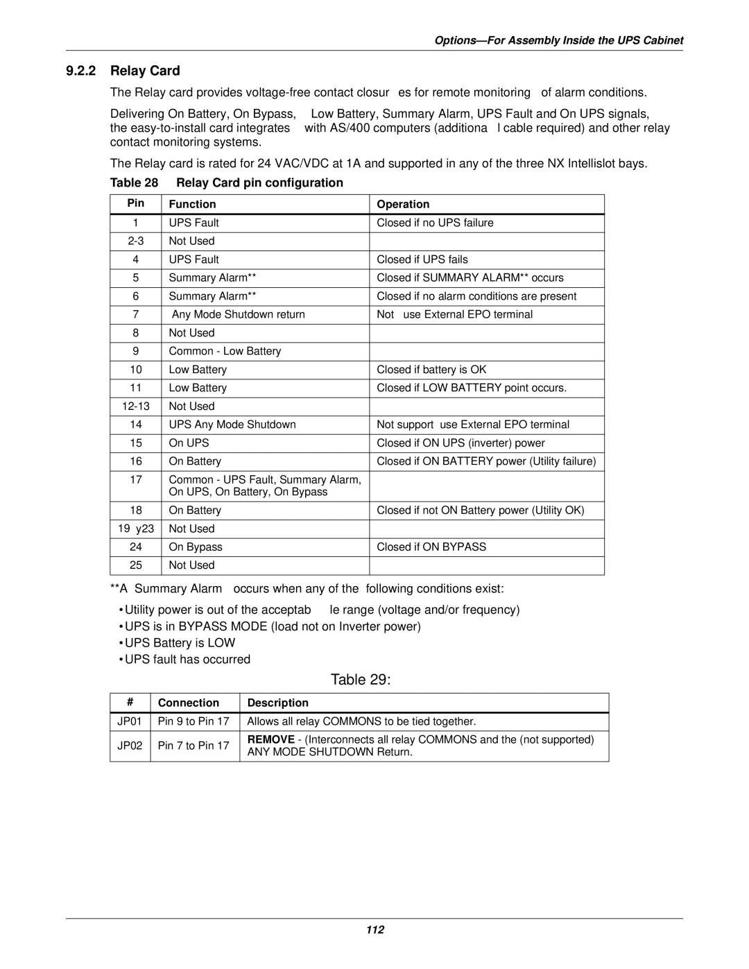
Relay Card pin configuration
Relay Card
Pin Function Operation
Connection Description
Multiport-4 Card
SiteNet MultiPort4 Intellislot pin assignment
Assignment
Pin Description
4 OC485 Web Card Modbus, Jbus, IGM Net
Remote Alarm Monitor
Comments
Conformity and Standards
Environmental characteristics
Compliance with European, international standards
Mechanical characteristics
Rectifier AC input mains
Intermediate DC circuit, battery
Inverter output to critical load
Bypass input
Net
Iti
Tin
That