MIB Description | cgmControl |
|
|
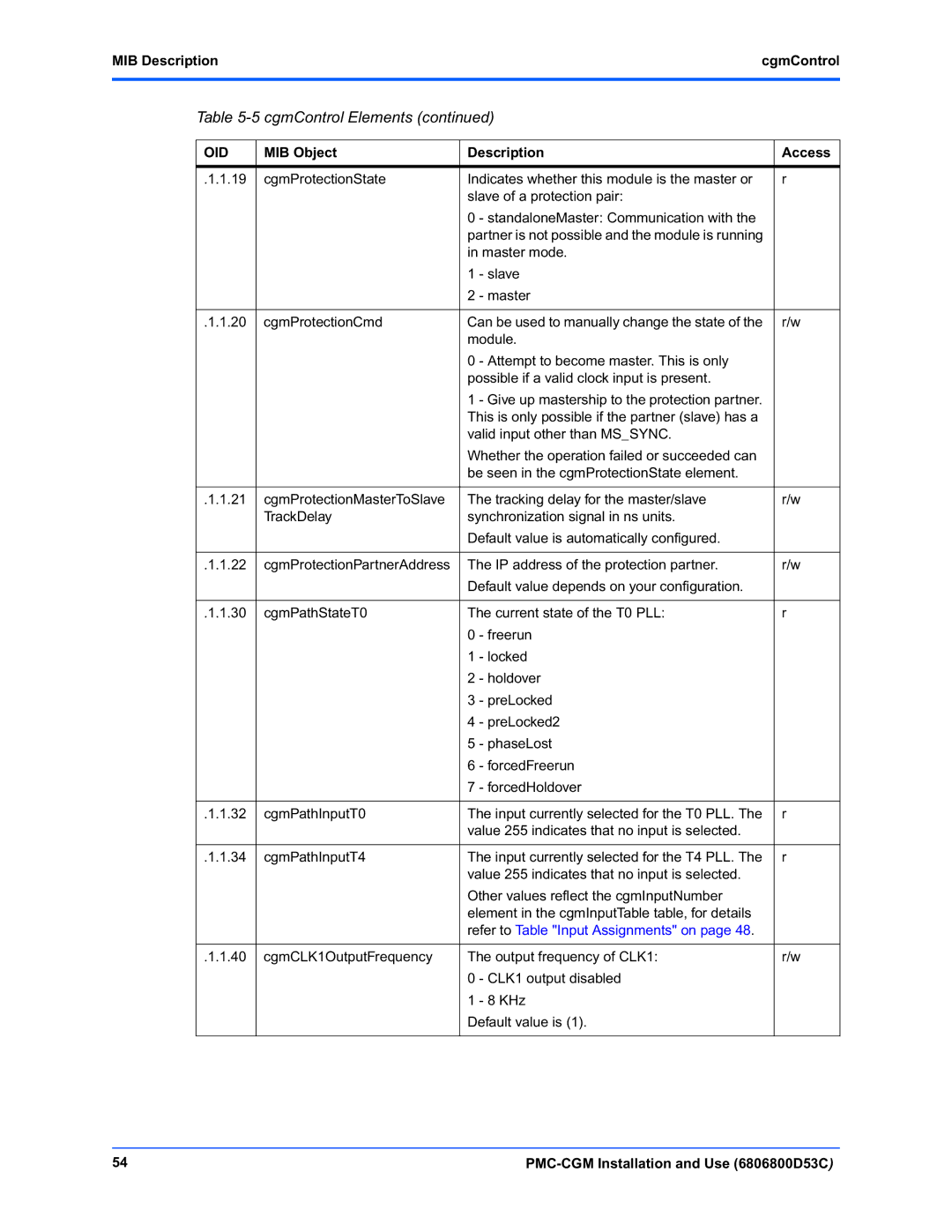
Table 5-5 cgmControl Elements (continued)
OID | MIB Object | Description | Access | |
|
|
|
| |
.1.1.19 | cgmProtectionState | Indicates whether this module is the master or | r | |
|
| slave of a protection pair: |
| |
|
| 0 | - standaloneMaster: Communication with the |
|
|
| partner is not possible and the module is running |
| |
|
| in master mode. |
| |
|
| 1 | - slave |
|
|
| 2 | - master |
|
|
|
|
| |
.1.1.20 | cgmProtectionCmd | Can be used to manually change the state of the | r/w | |
|
| module. |
| |
|
| 0 | - Attempt to become master. This is only |
|
|
| possible if a valid clock input is present. |
| |
|
| 1 | - Give up mastership to the protection partner. |
|
|
| This is only possible if the partner (slave) has a |
| |
|
| valid input other than MS_SYNC. |
| |
|
| Whether the operation failed or succeeded can |
| |
|
| be seen in the cgmProtectionState element. |
| |
|
|
|
| |
.1.1.21 | cgmProtectionMasterToSlave | The tracking delay for the master/slave | r/w | |
| TrackDelay | synchronization signal in ns units. |
| |
|
| Default value is automatically configured. |
| |
|
|
|
| |
.1.1.22 | cgmProtectionPartnerAddress | The IP address of the protection partner. | r/w | |
|
| Default value depends on your configuration. |
| |
|
|
|
| |
.1.1.30 | cgmPathStateT0 | The current state of the T0 PLL: | r | |
|
| 0 | - freerun |
|
|
| 1 | - locked |
|
|
| 2 | - holdover |
|
|
| 3 | - preLocked |
|
|
| 4 | - preLocked2 |
|
|
| 5 | - phaseLost |
|
|
| 6 | - forcedFreerun |
|
|
| 7 | - forcedHoldover |
|
|
|
|
| |
.1.1.32 | cgmPathInputT0 | The input currently selected for the T0 PLL. The | r | |
|
| value 255 indicates that no input is selected. |
| |
|
|
|
| |
.1.1.34 | cgmPathInputT4 | The input currently selected for the T4 PLL. The | r | |
|
| value 255 indicates that no input is selected. |
| |
|
| Other values reflect the cgmInputNumber |
| |
|
| element in the cgmInputTable table, for details |
| |
|
| refer to Table "Input Assignments" on page 48. |
| |
|
|
|
| |
.1.1.40 | cgmCLK1OutputFrequency | The output frequency of CLK1: | r/w | |
|
| 0 | - CLK1 output disabled |
|
|
| 1 | - 8 KHz |
|
|
| Default value is (1). |
| |
|
|
|
|
|
54 |
|