Controls, LEDs and Connectors | BITS Interface Connectors |
|
|
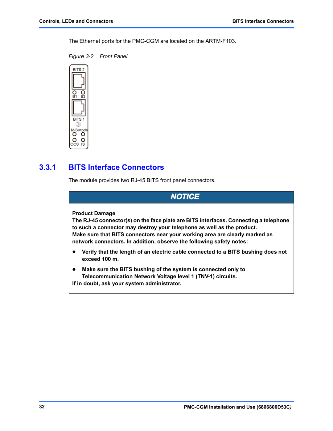
The Ethernet ports for the
Figure 3-2 Front Panel
3.3.1BITS Interface Connectors
The module provides two
Product Damage
The
Make sure that BITS connectors near your working area are clearly marked as network connectors. In addition, observe the following safety notes:
zVerify that the length of an electric cable connected to a BITS bushing does not exceed 100 m.
zMake sure the BITS bushing of the system is connected only to
Telecommunication Network Voltage level 1
If in doubt, ask your system administrator.
32 |