cgmControlMIB Description
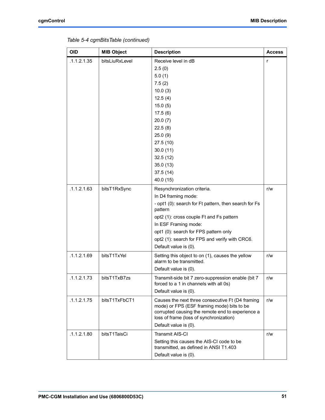
Table 5-4 cgmBitsTable (continued)
OID | MIB Object | Description | Access | |
|
|
|
| |
.1.1.2.1.35 | bitsLiuRxLevel | Receive level in dB | r | |
|
| 2.5 (0) |
| |
|
| 5.0 (1) |
| |
|
| 7.5 (2) |
| |
|
| 10.0 | (3) |
|
|
| 12.5 | (4) |
|
|
| 15.0 | (5) |
|
|
| 17.5 | (6) |
|
|
| 20.0 | (7) |
|
|
| 22.5 | (8) |
|
|
| 25.0 | (9) |
|
|
| 27.5 | (10) |
|
|
| 30.0 | (11) |
|
|
| 32.5 | (12) |
|
|
| 35.0 | (13) |
|
|
| 37.5 | (14) |
|
|
| 40.0 | (15) |
|
|
|
|
| |
.1.1.2.1.63 | bitsT1RxSync | Resynchronization criteria. | r/w | |
|
| In D4 framing mode: |
| |
|
| - opt1 (0): search for Ft pattern, then search for Fs |
| |
|
| pattern |
| |
|
| opt2 (1): cross couple Ft and Fs pattern |
| |
|
| In ESF Framing mode: |
| |
|
| opt1 (0): search for FPS pattern only |
| |
|
| opt2 (1): search for FPS and verify with CRC6. |
| |
|
| Default value is (0). |
| |
|
|
|
| |
.1.1.2.1.69 | bitsT1TxYel | Setting this object to on (1), causes the yellow | r/w | |
|
| alarm to be transmitted. |
| |
|
| Default value is (0). |
| |
|
|
|
| |
.1.1.2.1.73 | bitsT1TxB7zs | r/w | ||
|
| forced to a 1 in channels with all 0s) |
| |
|
| Default value is (0). |
| |
|
|
|
| |
.1.1.2.1.75 | bitsT1TxFbCT1 | Causes the next three consecutive Ft (D4 framing | r/w | |
|
| mode) or FPS (ESF framing mode) bits to be |
| |
|
| corrupted causing the remote end to experience a |
| |
|
| loss of frame (loss of synchronization) |
| |
|
| Default value is (0). |
| |
|
|
|
| |
.1.1.2.1.80 | bitsT1TaisCi | Transmit | r/w | |
|
| Setting this causes the |
| |
|
| transmitted, as defined in ANSI T1.403 |
| |
|
| Default value is (0). |
| |
|
|
|
|
|
| 51 |