Emerson PMC-CGM manual Controls, LEDs and Connectors, Front Panel Connectors and LEDs

Models: PMC-CGM

1 66
Download 66 pages 1.17 Kb
Page 31
Image 31

Controls, LEDs and Connectors

3

3.1Overview

This chapter describes:

zLayout

zFront panel connectors and LEDs

3.2Layout

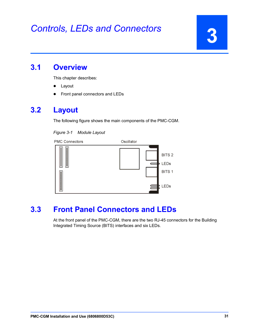
The following figure shows the main components of the PMC-CGM.

Figure 3-1 Module Layout

3.3Front Panel Connectors and LEDs

At the front panel of the PMC-CGM, there are the two RJ-45 connectors for the Building Integrated Timing Source (BITS) interfaces and six LEDs.

PMC-CGM Installation and Use (6806800D53C)

31

Page 31
Image 31
Emerson PMC-CGM manual Controls, LEDs and Connectors, Front Panel Connectors and LEDs