Section 6 • Troubleshooting
Slide Valve Actuators communicate problems discovered by internal diagnostics via LED blink codes. Only one blink code is displayed, even though it is possible that more than one problem has been detected.
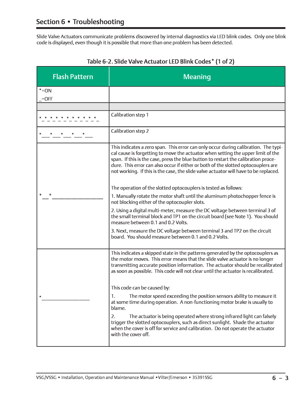
Table 6-2. Slide Valve Actuator LED Blink Codes* (1 of 2)
Flash Pattern
Meaning
*=ON |
|
| |
_=OFF |
|
| |
|
| ||
|
| ||
*_*_*_*_*_*_*_*_*_*_*_ | Calibration step 1 | ||
|
| ||
|
| ||
*___*___*___*___*___ | Calibration step 2 | ||
|
| ||
|
| ||
| This indicates a zero span. This error can only occur during calibration. The typi- | ||
| cal cause is forgetting to move the actuator when setting the upper limit of the | ||
| span. If this is the case, press the blue button to restart the calibration proce- | ||
| dure. This error can also occur if either or both of the slotted optocouplers are | ||
| not working. If this is the case, the slide valve actuator will have to be replaced. | ||
| The operation of the slotted optocouplers is tested as follows: | ||
*__*________________ | 1. Manually rotate the motor shaft until the aluminum photochopper fence is | ||
| not blocking either of the optocoupler slots. | ||
| 2. Using a digital | ||
| the small terminal block and TP1 on the circuit board (see Note 1). You should | ||
| measure between 0.1 and 0.2 Volts. | ||
| 3. Next, measure the DC voltage between terminal 3 and TP2 on the circuit | ||
| board. You should measure between 0.1 and 0.2 Volts. | ||
|
| ||
| This indicates a skipped state in the patterns generated by the optocouplers as | ||
| the motor moves. This error means that the slide valve actuator is no longer | ||
| transmitting accurate position information. The actuator should be recalibrated | ||
| as soon as possible. This code will not clear until the actuator is recalibrated. | ||
| This code can be caused by: | ||
*__________________ | 1. | The motor speed exceeding the position sensors ability to measure it | |
at some time during operation. A | |||
| |||
| blame. |
| |
| 2. | The actuator is being operated where strong infrared light can falsely | |
| trigger the slotted optocouplers, such as direct sunlight. Shade the actuator | ||
| when the cover is off for service and calibration. Do not operate the actuator | ||
| with the cover off. | ||
|
|
| |
VSG/VSSG • Installation, Operation and Maintenance Manual •Vilter/Emerson • 35391SSG | 6 – 3 |