Programming Guide
This section describes:
•
•Ethernet Link
•Symbols
•
•
•Switcher Error Responses
•Using the Command and Response Table
RS-232 Link
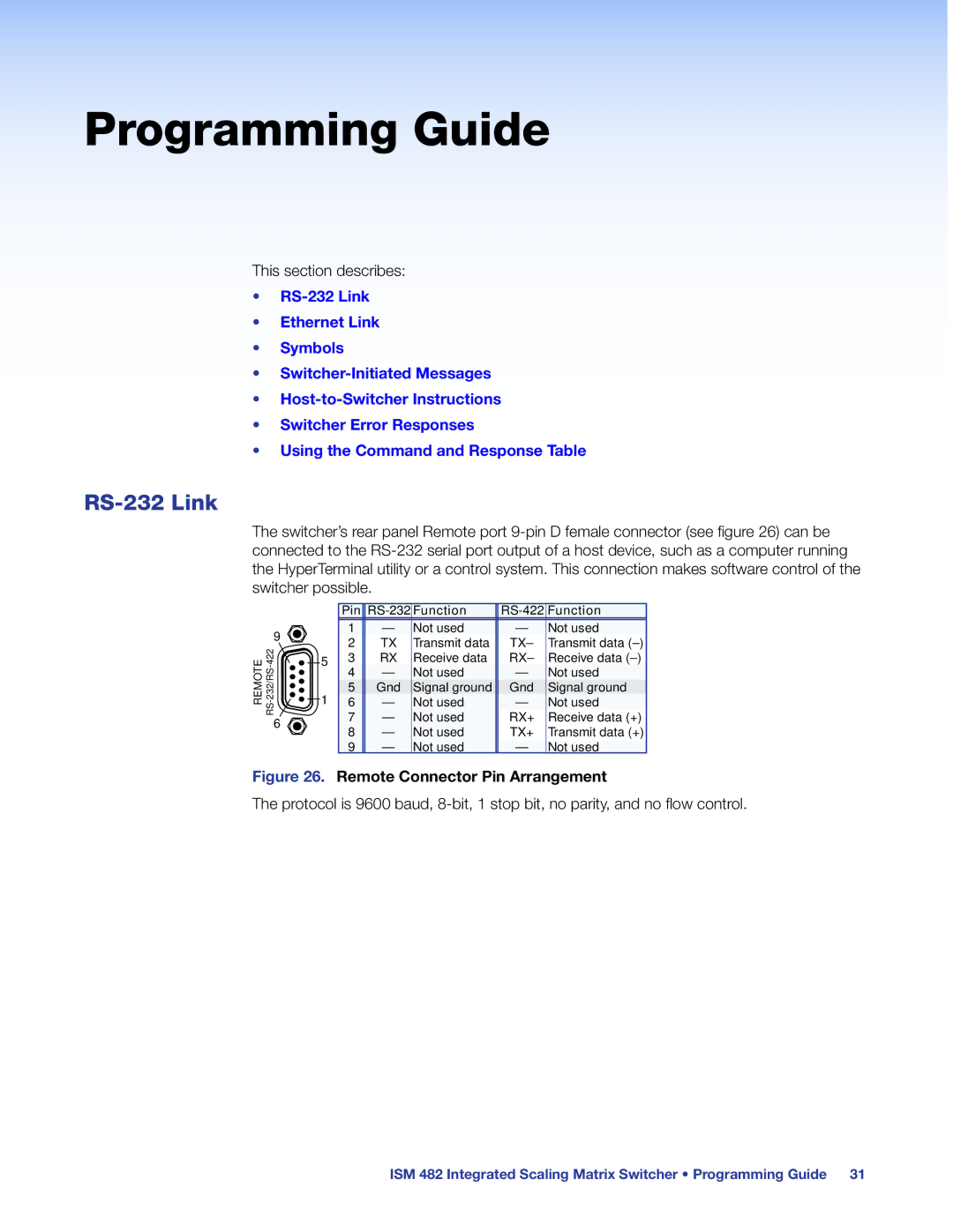
The switcher’s rear panel Remote port
9 ![]()
REMOTE 422- ![]()
| Pin |
| Function |
| Function | |
| 1 | — | Not used | — | Not used | |
| 2 | TX | Transmit data | TX– | Transmit data | |
5 | 3 | RX | Receive data | RX– | Receive data | |
4 | — | Not used | — | Not used | ||
| ||||||
1 | 5 | Gnd | Signal ground | Gnd | Signal ground | |
6 | — | Not used | — | Not used | ||
| 7 | — | Not used | RX+ | Receive data (+) | |
| 8 | — | Not used | TX+ | Transmit data (+) | |
| 9 | — | Not used | — | Not used |
Figure 26. Remote Connector Pin Arrangement
The protocol is 9600 baud,
ISM 482 Integrated Scaling Matrix Switcher • Programming Guide 31