|
| FILTER |
|
| CENTER |
| SIZE | NEXT |
| BRT/ | MENU |
1 | CONT |
|
| COLOR/ |
|
| TINT |
|
| VIDEO | OUTPUT |
8 |
|
INPUTS | 7 |
6 | 2 |
| 5 | AUDIO |
|
| 8 |
| 4 |
|
|
| 7 |
| 3 |
|
|
| 6 |
| 2 |
|
| 5 |
|
| 1 |
|
| 4 |
|
BLACK | 3 |
|
| 2 |
|
| 1 |
|
MUTE |
|
|
ADJUST
|
|
|
| 482 |
|
|
| ISM ATRIX | |
|
|
| ALIN | G M |
|
| N SC |
| |
| GRATIO |
|
| |
INTE |
|
|
| |
|
|
|
| |
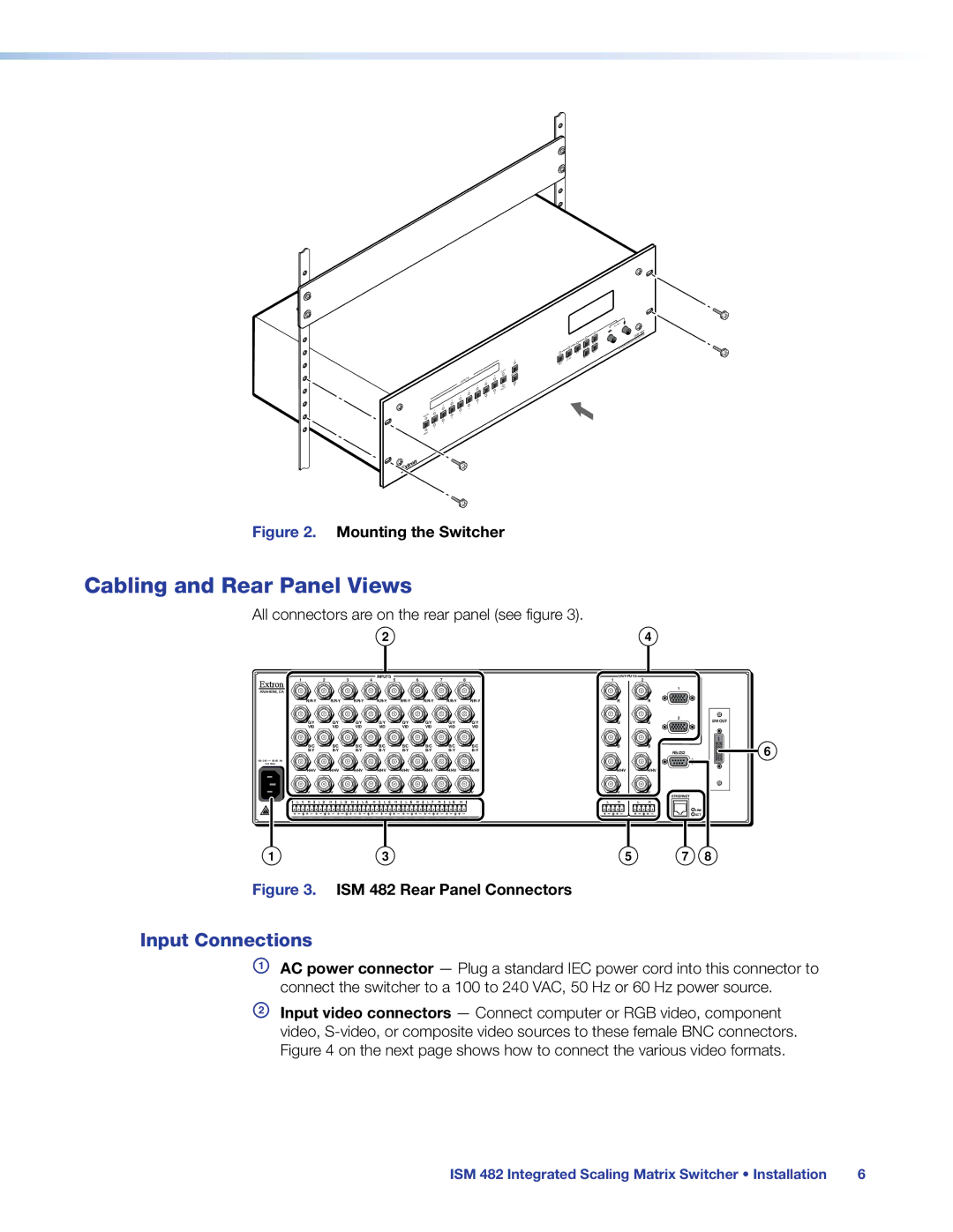
Figure 2. Mounting the Switcher
Cabling and Rear Panel Views
All connectors are on the rear panel (see figure 3).
|
|
|
| 2 |
|
|
|
|
| 4 |
1 | 2 |
| 3 | 4 INPUTS 5 |
| 6 | 7 | 8 | 1 OUTPUTS | 2 |
|
|
|
|
|
|
|
|
|
| 1 |
| R | R |
G/Y | G/Y |
| G/Y | G/Y | G/Y | G/Y | G/Y | G/Y |
VID | VID |
| VID | VID | VID | VID | VID | VID |
B/C | B/C |
| B/C | B/C | B/C | B/C | B/C | B/C |
| ||||||||
100- 240 50/60 Hz |
|
|
|
|
|
|
|
|
1.2A MAX. |
|
|
|
|
|
|
|
|
H/HV | H/HV |
| H/HV | H/HV | H/HV | H/HV | H/HV | H/HV |
V | V |
| V | V | V | V | V | V |
1 | 2 | 3 | 4 | 5 | 6 | 7 | 8 |
|
G | G | 2 | DVI OUT |
| |||
B | B |
|
|
|
|
| |
H/HV | H/HV |
|
|
V | V | ETHERNET |
|
|
|
|
LINK
ACT
6
1 | 3 | 5 | 7 | 8 |
Figure 3. ISM 482 Rear Panel Connectors
Input Connections
AAC power connector — Plug a standard IEC power cord into this connector to connect the switcher to a 100 to 240 VAC, 50 Hz or 60 Hz power source.
BInput video connectors — Connect computer or RGB video, component video,
ISM 482 Integrated Scaling Matrix Switcher • Installation | 6 |
