LCD Display
GStatus display — The
Menu Control Buttons
HMenu button — The Menu button enters and moves through the main menu system in the ISM (see “Front Panel Operations,” below, for details).
Next button — The Next button steps through the submenus in the ISM menu system (see “Front Panel Operations,” below, for details).
Adjustment Knobs
IAdjust ![]()
![]() (horizontal) and Adjust
(horizontal) and Adjust ![]() (vertical) knobs — The Adjust
(vertical) knobs — The Adjust ![]()
![]() and Adjust
and Adjust ![]() knobs change settings when used in conjunction with the picture adjustment buttons or the menu system. Rotate these knobs to change picture settings when one of the picture adjustment buttons is selected. In the menu system, rotate these knobs to scroll through the selection options and make adjustments.
knobs change settings when used in conjunction with the picture adjustment buttons or the menu system. Rotate these knobs to change picture settings when one of the picture adjustment buttons is selected. In the menu system, rotate these knobs to scroll through the selection options and make adjustments.
Front Panel Operations
Power
Power
on
The following paragraphs detail the
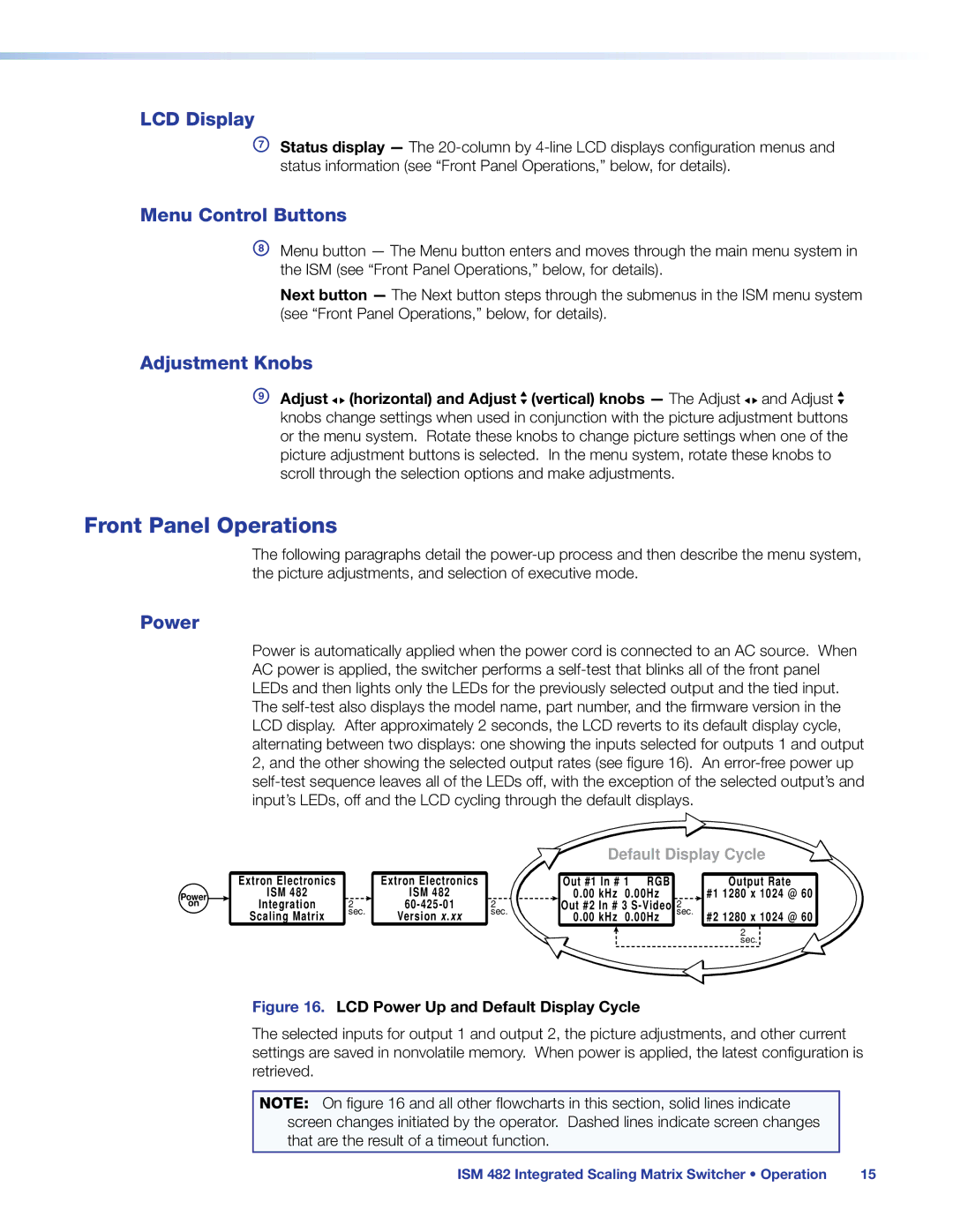
Power is automatically applied when the power cord is connected to an AC source. When AC power is applied, the switcher performs a
Default Display Cycle
Extron Electronics |
| Extron Electronics |
| Out #1 In # 1 | RGB | Output Rate |
ISM 482 |
| ISM 482 |
| 0.00 kHz 0.00Hz | #1 1280 x 1024 @ 60 | |
Integration | 2 | 2 | Out #2 In # 3 | 2 | ||
Scaling Matrix | sec. | Version x.xx | sec. | 0.00 kHz 0.00Hz | sec. #2 1280 x 1024 @ 60 | |
|
|
|
|
|
| 2 |
|
|
|
|
|
| sec. |
Figure 16. LCD Power Up and Default Display Cycle
The selected inputs for output 1 and output 2, the picture adjustments, and other current settings are saved in nonvolatile memory. When power is applied, the latest configuration is retrieved.
NOTE: On figure 16 and all other flowcharts in this section, solid lines indicate screen changes initiated by the operator. Dashed lines indicate screen changes that are the result of a timeout function.
ISM 482 Integrated Scaling Matrix Switcher • Operation | 15 |