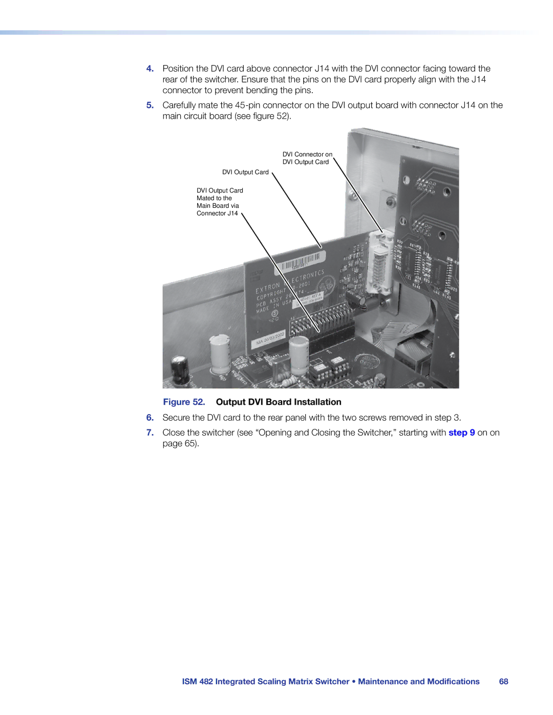
4.Position the DVI card above connector J14 with the DVI connector facing toward the rear of the switcher. Ensure that the pins on the DVI card properly align with the J14 connector to prevent bending the pins.
5.Carefully mate the
DVI Connector on
DVI Output Card
DVI Output Card
DVI Output Card
Mated to the
Main Board via
Connector J14
Figure 52. Output DVI Board Installation
6.Secure the DVI card to the rear panel with the two screws removed in step 3.
7.Close the switcher (see “Opening and Closing the Switcher,” starting with step 9 on on page 65).
ISM 482 Integrated Scaling Matrix Switcher • Maintenance and Modifications | 68 |