MGP 464 MGP 464 DI
Multi-Graphic Processor
Precautions
Safety Instructions English
Consignes de Sécurité Français
Sicherheitsanleitungen Deutsch
FCC Class a Notice
Page
Connecting to inputs 1 through
Quick Start MGP
Rack mounting the MGP
Virtual input connection examples
Configuring the MGP
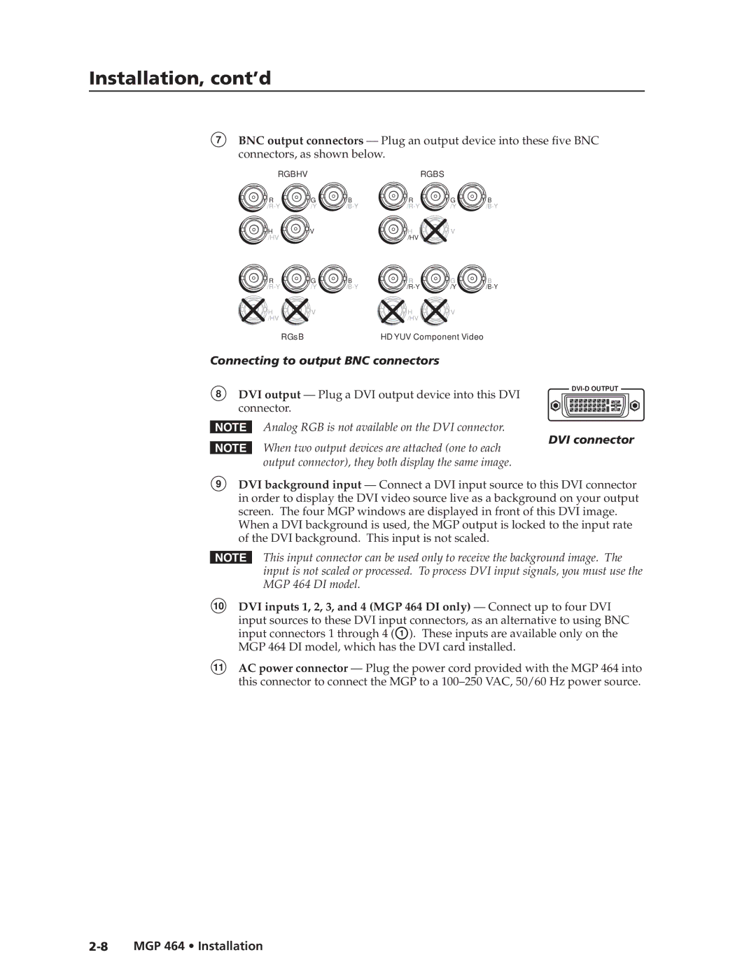
BNC output connectors
MGP 464 DI connection diagram
Quick Start MGP 464, cont’d
Adjusting the picture controls
Main menu
MGP 464 Quick Start QS-3
Use the Input Configuration menu to make
Horizontal and Vertical Start, Pixel Phase, Total
Auto Image
Press the Enter button
Table of Contents
Table of Contents, cont’d
Chapter Five Html Configuration and Control
MGP 464 Table of Contents Iii
Appendix a Specifications, Part Numbers, and Accessories
Iv MGP 464 Table of Contents
Rev B
One
Features
Introduction
About This Manual
About the MGP 464 Multi-Graphic Processor
Application Diagrams
Connection diagram for MGP 464 DI
Introduction, cont’d
Extron MGP
Two
Installation
Installation Overview
Mounting the MGP
Tabletop use
Rack mounting procedure
Installation, cont’d
Installing or Replacing Button Labels
MGP as follows
Replacing a button label
Rear Panel Features
Connecting to RGB/HD/VIDEO inputs 1 through
MGP 464 rear panel
Virtual input connector configuration examples
Activity LED This yellow LED blinks to indicate
Link LED This green LED lights to indicate a good
Pin RS-422 function Description
LAN port defaults
MGP’s IP address Gateway IP address Subnet mask Dhcp off
Connecting to output BNC connectors
DVI connector
MGP 464 DI model, which has the DVI card installed
DVI output Plug a DVI output device into this DVI
Three
Front Panel Features
Operation
MGP 464 front panel
MGP 464 Operation
RS-232/422 port, see Rear Panel Features in , Installation
Baud Data bits Stop bit No parity Always RS-232
Power-up and Default Cycle
Mm connector cable for the configuration port
Default cycle
Operation, cont’d
Window Select Buttons
Input Selection
Selecting an input
Muting an input
Menus, Configuration, and Adjustments
Using the menus
Menu system overview
Main menu flow
When finished with Auto Image, do one of the following
Auto Image menu
Auto Image menu flow
Input Configuration menu
Input Configuration menu flow
Input configuration submenu adjustments
Output Configuration menu
Output Configuration menu flow
Total pixels
Active pixels
Resolution and Refresh Rate submenu
Resolution Refresh Rates 50 Hz 60 Hz 72 Hz 96 Hz
Output Type submenu
100 Hz 120 Hz
Window Configuration menu
Window Configuration menu flow
Sync Polarity submenu
Window Priority submenu
Window Border submenus
Window Effect submenu
Available effects
Out from the center to the four edges of the window
Effect Duration submenu
Press the Next button until Effect Duration is displayed
Background Capture menu
Background Capture menu flow
Comm./IP Configuration menu
Viewing serial port and IP settings
Screen displays the message Detail = Confirm
Within 20 seconds
Making changes to the serial port and IP configuration
Communication/IP Configuration menu flow
Advanced Configuration menu
Advanced Configuration menu flow
Blue Mode submenu
Background Color submenu
Test Pattern submenu
Test patterns available for the MGP
Adding and Configuring Window Text
Internal Temperature screen
Factory Default submenu
Button Display Function Range Adjust Knob
Button Display Function Range Adjust Knob
Image Zoom
Memory Presets
Window presets
Saving a window preset
Auto Memories
Window Preset #001 Saved
Recalling a window preset
Input presets
Default presets
Factory default preset configurations
Brightness Contrast Color
Additional Features
Freeze mode
Locking the front panel executive mode
Resetting
Reset Mode Comparison/Summary
Mode Activation Result Purpose/Notes
Preliminary
Four
Software Configuration and Control
Setting Up Serial Communication
Connector pin assignments
Front panel RS-232 configuration port pin assignments
Using Simple Instruction Set SIS Commands
Communication software
Host-to-MGP communications
MGP-initiated messages
Software Configuration and Control, cont’d
Error responses
Telnet and Web communications
Ascii to hexadecimal character conversion table
Web browser
Escape hex 1B Must not be encoded Carriage return hex 0D
Symbol definitions
= CR/LF carriage return/line feed hex 0D 0A
X50
X50@
= Secam
Command Ascii Telnet Response Additional description
Software Configuration and Control
X50 * X50@ Out X50@
X50 * X50# \ X50 Typ X50#
SIS Programming and Control, cont’d
19 # X52$ # Wpe X52$
X52$
X50@ + C
X50@ C
Control, cont’d
X50@ Ivp X52
X50@ * X52@ X50@ Whs X52@
X50@ X52@
X50@ * X52@ X50@ Wvs X52@
SIS Programming and Control
Cont’d
X50@ I Y X50@ , X52! * X52! * X52# * X52#
X50@ + X50@ Wzm
X50@ X50@ Wzm
X50@ +
X50@ * X51$
X50 , X50 NI Nmi X50
X50 NI
X51# , X50 NP Nmp X51#
X50 * X51@ Hst X50 * X51@
X50 + Hst X50 * X51@
X50 Hst X50 * X51@
X50 X51@
13 * X50 * X51& # Aln X50
13 * X50 + # Aln X50
13 * X50 # Aln X50
13 * X50 # X51
Executive mode
X50$ J Tst X50$
X50$
X50@ Chn X50 Typ X50# Std X50 Blk X%
SIS Programming
X50@ Tlc X50%
Special functions
Special functions
14 * X50@ * X\ # X50@ Txb X\
14 * X50@ #
16 * X50@ * X\ # X50@ Txc X\
17 * X50@ #
X50@ * X\ # X50@ Brd X\
X50@ #
22 * X52% * X52% * X52% #
Ubk X52% * X52% * X52%
X50 Flm
Img X50@
Auto image
%2A X! % %2A X2 %2A X2! RS X@
Bi-directional serial data port
X2& = 7 or X2* = 1 or View serial port parameters
X2 CY %2A X2 CY Cpn X! Cty
X3 , X3! CF
Cpn X! Cfl X3
X2 * X2# * X2! CE
X6 TC
Ethernet data port
Firmware version requests
X1! = firmware version to two decimal places
Ver04 * X1! plus web ver.-desc-UL date/time
02 * 1.66-MGP464 Series -Mon, 14 Jan 2008 170346 GMT
MGP 464 is MGP 464 DI is
X3% , X3 , X3& , X3* E
X5$
X3% , X3 , X3& , X3 , X3* E
X3% , X3 , X3& , X4$ FE
Command Ascii Telnet URL Encoded Web Response
X4% , X4 , X4& CR Ipr X4% , X4
X4% CR
X4% SM Eml X4%
Programming and Control, cont’d
X3$ CX
X1$ CI
X1$ CI Ipx X3$
X3$
Control
X5@
X2@ CV
X2@
Pvl X5@
Programming
34 MGP
Re-map port designations
Listing connections
Mail server setup commands
Directory commands
Reset Zap / Erase commands
X1$ , X1% CM X1$ %2C X1% CM Ipm X1$ , X1%
Installing the software
Windows-based Control Software
Link to the installation software on the MGP 464 CD
File Download window
Downloading the MGP 464 software from the Web
\Program Files\Extron\MGP464
Called MGP464 in the following location on the computer
Select TCP/IP if you are using the LAN port
Starting the control program
Comm Port Selection window with TCP/IP and RS232 tabs
MGP 464 window
From the Help pull-down menu, or press the F1 key
Five
Html Configuration and Control
Accessing the Web Pages
Example of an Enter Network Password dialog box
MGP 464 Html Configuration and Control
Viewing System Status
MGP
System Status screen
Html Configuration and Control, cont’d
Using the Configuration
System Settings screen
System Settings screen
Scaler I/O Settings screen
Scaler I/O Settings screen
Configuring the inputs
Naming inputs
Selecting the video signal type
Configuring the output
Enabling/disabling blue mode
Test patterns available on the MGP
Window Settings screen
Window Settings screen
Setting window priority
Passwords screen
Passwords screen
Assigning a password
Clearing a password
Setting up e-mail alerts
If your MGP has a password assigned, enter it
Email Alerts screen
Email Alerts screen top portion
Firmware Upgrade screen
Setting up Smtp authorization
Firmware Upgrade screen
Mail IP Address field. The Edit button changes to Save
Downloading the firmware
To obtain the latest version of MGP 464 firmware
Updating the firmware on the MGP
Choose file window
Using the File Management
Firmware Version on the Firmware Upgrade screen
File Management screen
Uploading files
Adding a directory
Other file management activities
Delete all files Click the Delete All button
Using the Control
Picture Controls screen
Picture Controls screen
Window Selection
Input sections
Window Controls
Image Controls
Preliminary
Presets screen
Presets screen
Window Presets
Window Presets section, you can do the following
Naming a window preset
Symbols / + space
Numerals 0 through
Saving creating a window preset
Selecting a window preset transition effect
Input Presets
From the Window Effect menu, select Real time motion or Cut
Using the Background
Selecting a background color
Displaying a background image
Add Image field on the Image Settings screen
Uploading an image
To upload a bitmap image to the MGP
Selecting a background image
Six
Application 1 Connecting the MGP 464 to a Matrix Switcher
MGP 464 connected to a matrix switcher
Special Applications
Are described, along with their requirements for the MGP
Setting up the MGP to work with the switcher
Connecting the matrix switcher to the MGP
Special Applications, cont’d
Preliminary
Preliminary
Setting up MGPs for daisy-chaining
Daisy-chain configuration examples
Repeat step d for the third MGP if appropriate
AAppendix a
Specifications, Part Numbers, and Accessories
Specifications
MGP 464 Specifications, Part Numbers, and Accessories
24 bit, 8 bits per color 160 MHz standard
Enclosure dimensions
Control/remote processor/decoder/scaler
Specifications, Part Numbers, and Accessories, cont’d
Part Numbers and Accessories
Optional accessories
Included parts
AppendixBB
Firmware Upgrade Guide
Using the LCD display at power-on
Using a Web browser
Power-up cycle flow diagram
MGP 464 Firmware Upgrade Guide B-3
Next time you enter your MGP 464’s IP address
System Status Web
Firmware Upgrade Guide, cont’d
Using the Windows-based configuration software
Downloading the firmware
About... screen
Updating using the Web pages
Enter Network Password dialog box
MGP 464 Firmware Upgrade Guide B-5
Updating the Firmware
Choose file window with firmware file selected
Updating using the Windows-based control software
MGP 464 Firmware Upgrade Guide B-7
Open window with firmware file selected
Extension must be .S19
Updating using the Firmware Loader
Firmware update progress bar
On the Extron Web page, click the Download tab
\Program Files\Extron\FWLoader
Default is
MGP 464 Firmware Upgrade Guide B-9
Firmware Loader connection tabs
Firmware Loader file selection screen
Preliminary
Extron Electronics, Europe
Asia Japan
Extron Electronics. All rights reserved
Extron USA East