Mini Twisted Pair Matrix Switcher
Mtpx Plus Series
Sicherheitsanleitungen Deutsch
Safety Instructions English
Consignes de Sécurité Français
Instrucciones de seguridad Español
FCC Class a Notice
Page
Table of Contents
Table of Contents, cont’d
Command/Response Table for IP-specific SIS Commands
Iv Mtpx Plus Twisted Pair Matrix Switchers Table of Contents
Mtpx Plus Twisted Pair Matrix Switchers Table of Contents
Vi Mtpx Plus Twisted Pair Matrix Switchers Table of Contents
One
About this Manual
About the Mtpx Plus Twisted Pair Matrix Switchers
Mtpx Plus Twisted Pair Matrix Switchers Introduction
Extron Mtpx Plus
Mtpx Plus Twisted Pair Matrix Switchers Introduction
Twisted pair TP cable advantages
Transmission distances
Component Video
Mtpx
Definitions
Skew equalization
Features
Tie any input to any or all outputs
Mtpx Plus Twisted Pair Matrix Switchers Introduction
Introduction, cont’d
Two
UL guidelines
Mounting the Switcher
Mtpx Plus Twisted Pair Matrix Switchers Installation
Mounting instructions
Rear Panel Cabling and Settings
Shows the rear panel of the Mtpx Plus
Signal inputs
Transmitters to these RJ-45 female connectors
Video RGB sources to these 15-pin HD female connectors
Connector. High impedance is generally over 800 ohms
VTT receivers to these RJ-45 female connectors
Signal outputs
Connectors
RS-232 output inserts
Captive screw connector wiring for audio output
RS-232/RS-422 connection
Ethernet connection
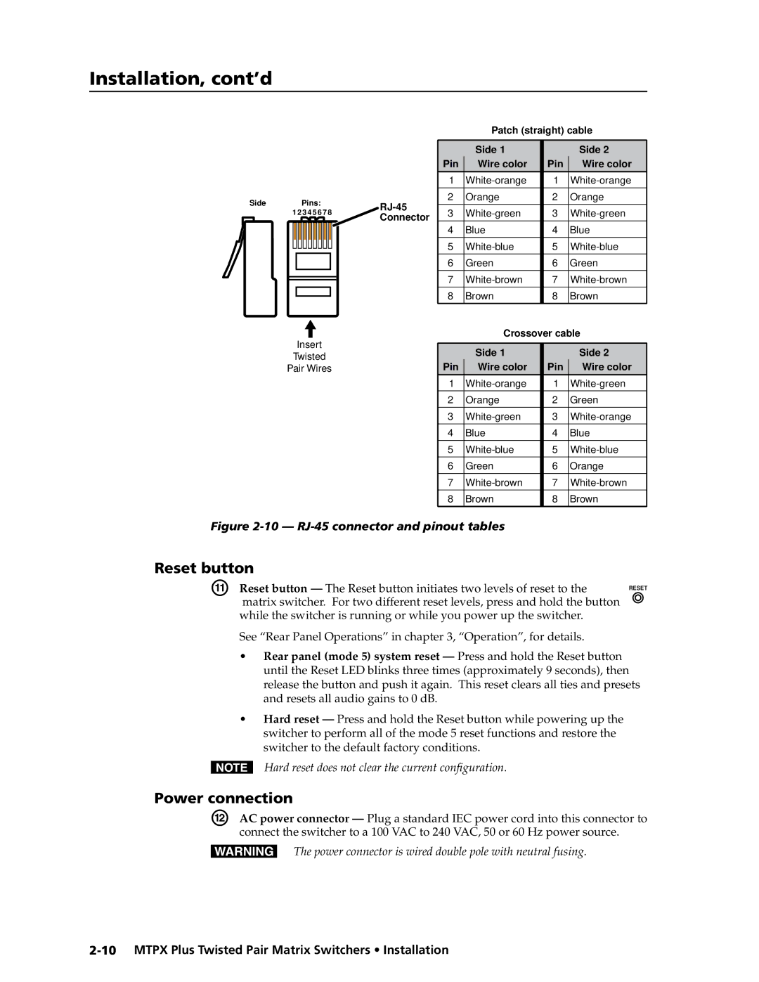
RJ-45 connector wiring
Cabling
Reset button
Power connection
Front Panel Configuration Port
70-335-01figure 2-12, can be used for this connection
Baud No parity Data bits Stop bit No flow control
Installation, cont’d
Three
Front Panel Controls and Indicators
Mtpx Plus Twisted Pair Matrix Switchers Operation
Input and output buttons
Primary functions
Secondary functions
Identify the selected input
Select a preset. See Using presets on
Select an input
On and off. See Background illumination on
Control buttons
Wire pair on
Preset mode to activate a previously-defined preset
Preset mode is active
View button The View button has two primary functions
Mtpx Plus Twisted Pair Matrix Switchers Operation
See Performing a system reset from the front panel on
Controls
Button icons
Executive modes on
Front Panel Operations
Definitions
Power
Front panel security lockouts
Creating a configuration
Example 1 Creating a set of video and audio ties
Press and release the Esc button figure
Press and release the input 5 button figure
Current configuration -9 is now
Press and release the Enter button figure
Example 2 Adding a tie to a set of video and audio ties
Press and release the input 5 button figure
Press and release the output 1 button figure
Current configuration -15 is now
Press and release the Enter button figure
Example 3 Removing a tie from a set of video and audio ties
Press and release the Esc button figure
19 Deselect the output
Viewing a configuration
Lights red
Video button and the Audio button figure
24 Select an input
Press and release the Video button to deselect video figure
26 Deselect audio and select video to view video ties only
Grouping
4 5 6 7 8 9
Allow the mode to time out after approximately 30 seconds
Buttons that may be lit
Outputs
Example 5 Grouping inputs and outputs
Press and release the Enter button to select group 1 figure
32 Assign inputs and outputs
35 Deselect I/O Group mode
Using presets
16 x 32, 32 x 16, and 32 x 32 matrix sizes
Example 6 Saving a preset
Press and release the Input 1 button
Example 7 Recalling a preset
Press and release the Preset button figure
43 Select the preset
Muting and unmuting audio/RS-232 outputs
Example 8 Muting and unmuting an audio/RS-232 output
Release the Audio button figure
46 Select audio only
Viewing and adjusting the TP input audio level
VCR
Example 9 Viewing and adjusting an input audio level
51 Clear all selections
Output button audio gain and attenuation display
Mtpx Plus
53 Select an input
55 Adjust the input audio level
Press and release the Audio button figure
Viewing and adjusting the local output volume
Reading the displayed volume
Audio volume display
Push Esc button twice more 7% + 1.5% + 1.5% = 10% volume
Example 10 Viewing and adjusting a local output volume level
Press and release the output 1 button figure
10 11 13 14 15
Press and release the Audio button figure
Lit Buttons Unlit Buttons
Setting the front panel locks Executive modes
Selecting Lock mode 2 or toggling between mode 2 and mode
Switcher
Performing a system reset from the front panel
Background illumination
Defining the audio/RS-232 wire pair
4 5 6 7 8 9
Input Configuration mode figure
Selecting the rear panel Remote port protocol and baud rate
Rear Panel Operations
Reset Mode Comparison/Summary
Activation Result Purpose/Notes
Performing a hard reset reset
If necessary, turn off power to the switcher
To the switcher figure
Performing soft system resets resets 3, 4,
Or three times absolute reset figure
Video Adjustments
Troubleshooting
Optimizing the Audio
Configuration Worksheets
Worksheet example 1 System equipment
Displayed in the main hall output
Worksheet example 2 Daily configuration
This example
Audio from the presenter’s microphone input 3 is
Worksheet example 3 Test configuration
79 Worksheet example 3 Test configuration
Button switchers configuration worksheet
Preset #
Operation, cont’d
Button switchers configuration worksheet
Operation, cont’d
Four
Serial Ports
Default protocol for both ports is as follows
Mtpx Plus Twisted Pair Matrix Switchers Programmer’s Guide
Rear panel Remote port
Front panel Configuration port
This port is hardwired for RS-232 only
Programmer’s Guide, cont’d
Ethernet LAN Port
Establishing a connection
Default IP addresses
Connection timeouts
Number of connections
Host-to-Switcher Instructions
Switcher-Initiated Messages
Using Verbose Mode
E27 Invalid event number
Switcher Error Responses
E26 Maximum number of connections exceeded
E28 Bad filename / file not found
Symbol definitions
Using the Command/Response Tables
Command/Response Table for SIS Commands
X1 =
X1$ =
X2 =
X3! =
X3# =
Command Ascii command Response Additional
Description
EX%Lrpt
EX# *X& Ipek
EX# Ipek
EX#*X1+Iseq IseqX#*X*X*X
EX#*X*X*XIseq
IseqX#*X*X*X
EX#*X1-Iseq IseqX#*X*X*X
X1$
EX1$Opol
EX1#*X1$Opol OpolX1#*X1$
EX1#Opol X1$
X1% OutX1% VolX1
X1% *X1 OutX1% VolX1
X1% +V OutX1% VolX1
X1%
# +G InX# AudX1
# *X1& G InX# AudX1
# *X1 g InX# AudX1
# -G InX# AudX1
EX2# 1X2# 2 ...X2# n
EX#,X2!NI NmiX#,X2
EX#,X2!NO NmoX#,X2
EX2# 1X2# 2 ...X2# n O GroX2# 1X2# 2X2# 3 ...X2# n
+X2P0*! SprX2 +X2PX!*X@!X!*X@%X!*X@$ ... X!*X@
Direct write process
EX2@*X2ZP
Lock executive modes
X1%V
X2$1X2$2 ... X2$n
EX2*X@*1VC X!nX!n+1...X!n+15Vid
X2@
EX2*X@*2VC X!nX!n+1...X!n+15Aud
EX2@*X2*1*1VC X!nX!n+1...X!n+15Vid
EX2@*X2*1*2VC X!nX!n+1...X!n+15Aud
EDF
VX2XX2&AX2XX2
X2 -X3
X3! X3! X3! X3! X3! X3@ X3# X3#
Command/Response Table for IP-specific SIS Commands
= 20 ms, default
IpzX4$
IptX4@
X4#
X4$
Special Characters
Five
Scroll to the desired program and click Install figure
Matrix Switchers Control Program
Installing the software
Mtpx Plus Twisted Pair Matrix Switchers Matrix Software
Ethernet protocol settings
Software operation via Ethernet
Using the Matrix Switcher Control software
Comm Port Selection window -3 appears
Extron Matrix Switchers Control Program window blank
IP Settings/Options window
Sample program window complete
Control program IP setting/options window
Matrix IP Address field
Subnet Mask field
Extron Name/Descriptor field
Gateway IP address field
Hardware Address field
Sync Time to PC button
Use Dhcp check box
Date, Time local, and GMT offset fields
Use Daylight Savings check box
Mail Server IP Address field
Mail Server Domain Name field
Mail Addressee fields
Mtpx Plus Twisted Pair Matrix Switchers Matrix Software
Updating firmware
10 Downloading firmware upgrade files
Chapter, steps 1 through 4, starting on
Switcher LAN port. See , Installation, for more details
Start the Matrix Switchers Control Program and connect to
Ethernet-connected firmware upload
Serial-port-connected firmware upload
12 Firmware loading
13 Confirm window
Uploading Html files
Windows buttons, drop boxes, and trashcan
Windows menus
File menu
15 Mtpx Configuration Settings Window
Tools menu
16 Mtpx Picture Settings window
Audio-input Configuration selection
White Not displayed for the Mtpx Plus
Preferences menu
Ties as Lines Displays ties as lines figure
Control Program window -6. You can place icons
Using Emulation mode
Using the help system
Optimizing the Video
Mtpx level/peaking setting
To open the Mtpx Picture Settings window -16 on
MTP transmitter Pre-Peak selection
Mtpx skew setting
MTP receiver to be optimized
MTP Receiver level/peaking setting
Mtpx Plus Pre-Peak selection
Product manual
Button-Label Generator Program
22 Location of software on the web site
Using the Button-Label Generator software
23 Extron’s Button-Label Generator window
Six
Access the switcher using Html pages as follows
Mtpx Plus Twisted Pair Matrix Switchers Html Operation
Download the Startup
System Status
System Status
Unit Name field
System Settings
IP Settings fields
Dhcp radio buttons
Firmware field
IP Address field
MAC Address field
Model field
Date/Time Settings fields
Date/Time Settings fields -4 provide a location for viewing
Appears the year drop box is selected in figure
Passwords
System Settings
Email Settings
Mail IP Address field
Setting up Smtp authorization
Domain Name field
Email address fields
Click the Configuration tab
Firmware Upgrade
Access the Mtpx Plus switcher using Html pages
Click the Browse button. An open file window appears
File Management
Click the Browse button
Browse through your system and select the desired files
User Control
By clicking the Control tab
Gray buttons indicate no ties
Picture Settings
Creating a tie
Changing the input level/peaking
Toggling output pre-peaking on and off
Changing the skew
Change an input’s or output’s skew setting as follows
Setting 2 ns at a time as follows
Shifted to the left
Mtpx Configuration
13 Mtpx Configuration
Settings
Output volume. Access the I/O Settings page -14 by clicking
Settings link on the Control
Changing the input gain and attenuation
15 Input Audio Level drop box
Changing the output volume level
Muting and unmuting an audio or RS-232 output
Audio volume adjustment settings
Global Presets
Saving a preset
Recalling a preset
Space + ~ , @ = ‘ ’ semicolon colon \ and ?
AAppendix a
Default address
Mtpx Plus Twisted Pair Matrix Switchers Ethernet Connection
Ethernet Link
Connecting as a Telnet client
Pinging to determine the Extron IP address
Pinging to determine the Web IP address
Telnet tips
Open
Escape character and Esc key
Close
Local echo
Set carriage return-line feed
Help
Local and remote devices
Subnetting a Primer
Gateways
IP addresses and octets
Determining whether devices are on the same subnet
Unmasked octets are compared indicated by ? in figure A-6
Ethernet Connection, cont’d
AppendixBB
Specifications
Reference Information
Audio
Reference Information, cont’d
Matrix switcher part numbers Part number
Part Numbers and Accessories
Mtpx Plus matrix switcher part numbers
Included parts Replacement part Number
Accessories
Cables
Male-to-male VGA molded connector cables Part number
Connector Part number
Installing labels in the matrix switcher’s buttons
Button Labels
Button label blanks, 16-button strips
Reference Information, cont’d
Extron’s Warranty
Extron Electronics, Europe
Extron USA West