Voyager 3000 User Guide

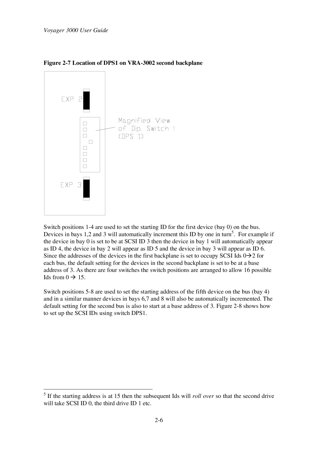
Figure 2-7 Location of DPS1 on VRA-3002 second backplane

Switch positions 1-4 are used to set the starting ID for the first device (bay 0) on the bus. Devices in bays 1,2 and 3 will automatically increment this ID by one in turn5. For example if the device in bay 0 is set to be at SCSI ID 3 then the device in bay 1 will automatically appear as ID 4, the device in bay 2 will appear as ID 5 and the device in bay 3 will appear as ID 6. Since the addresses of the devices in the first backplane is set to occupy SCSI Ids 0à2 for each bus, the default setting for the devices in the second backplane is set to be at a base address of 3. As there are four switches the switch positions are arranged to allow 16 possible Ids from 0 à 15.

Switch positions 5-8 are used to set the starting address of the fifth device on the bus (bay 4) and in a similar manner devices in bays 6,7 and 8 will also be automatically incremented. The default setting for the second bus is also to start at a base address of 3. Figure 2-8 shows how to set up the SCSI IDs using switch DPS1.

5If the starting address is at 15 then the subsequent Ids will roll over so that the second drive will take SCSI ID 0, the third drive ID 1 etc.
2-6

Page 26
Image 26
First Virtual Communications 3000 user manual Location of DPS1 on VRA-3002 second backplane