Installation and Setup
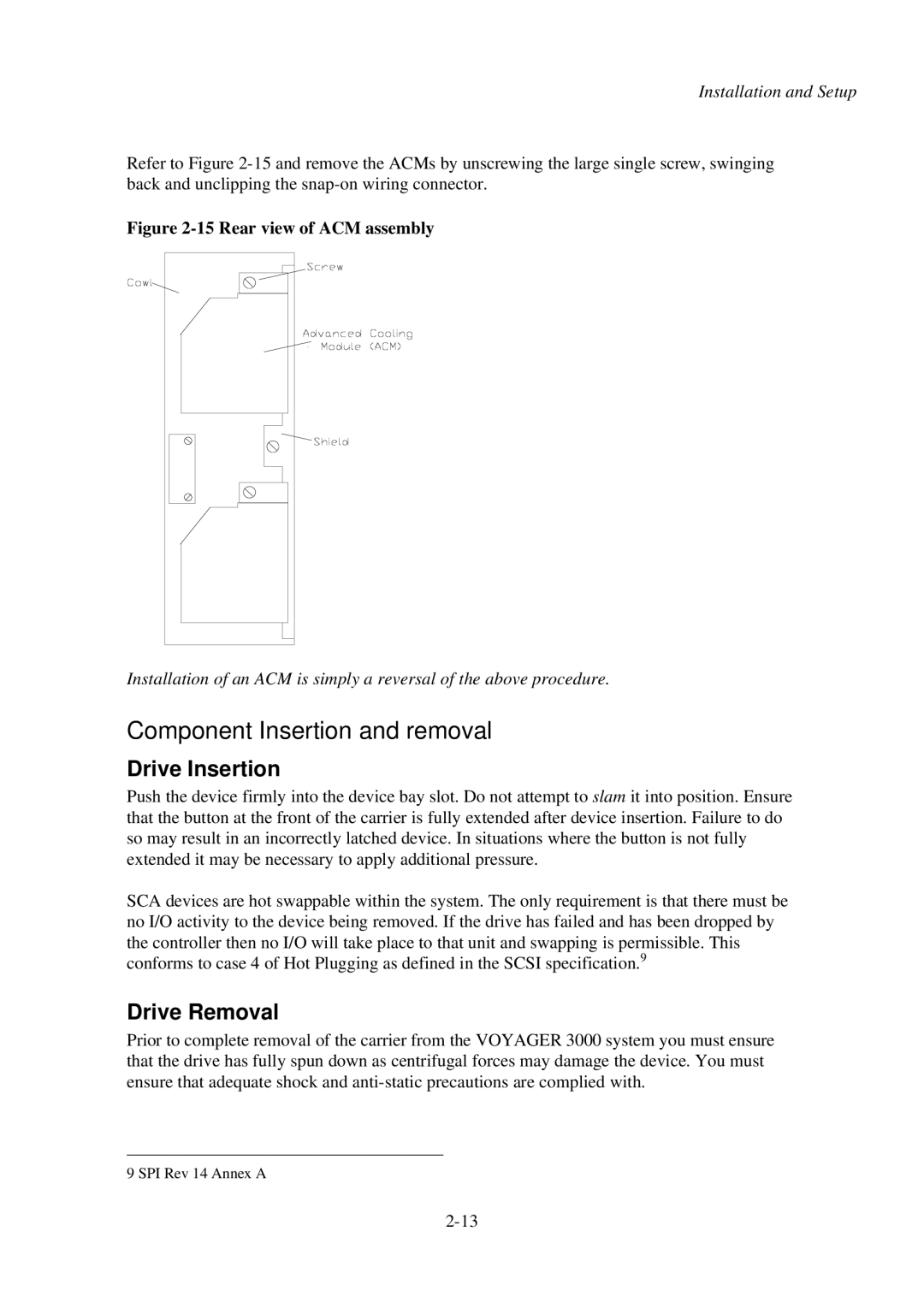
Refer to Figure
Figure 2-15 Rear view of ACM assembly
Installation of an ACM is simply a reversal of the above procedure.
Component Insertion and removal
Drive Insertion
Push the device firmly into the device bay slot. Do not attempt to slam it into position. Ensure that the button at the front of the carrier is fully extended after device insertion. Failure to do so may result in an incorrectly latched device. In situations where the button is not fully extended it may be necessary to apply additional pressure.
SCA devices are hot swappable within the system. The only requirement is that there must be no I/O activity to the device being removed. If the drive has failed and has been dropped by the controller then no I/O will take place to that unit and swapping is permissible. This conforms to case 4 of Hot Plugging as defined in the SCSI specification.9
Drive Removal
Prior to complete removal of the carrier from the VOYAGER 3000 system you must ensure that the drive has fully spun down as centrifugal forces may damage the device. You must ensure that adequate shock and
9 SPI Rev 14 Annex A