2635A

Users Manual

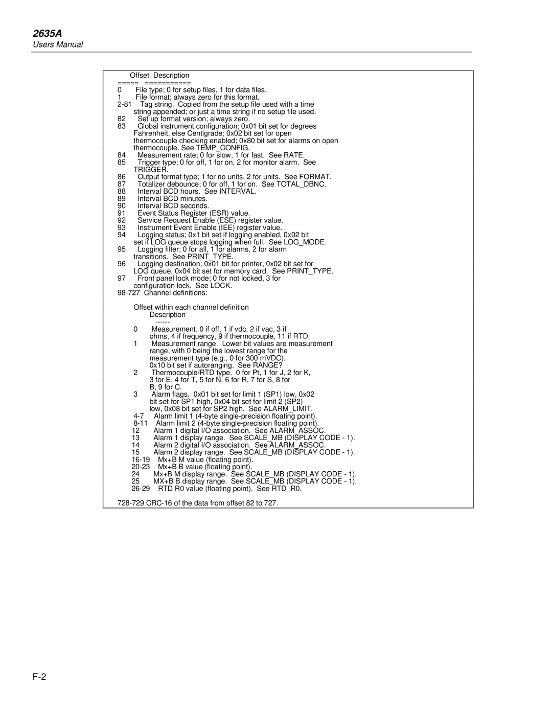
Offset Description

================

0File type; 0 for setup files, 1 for data files.

1File format; always zero for this format.

2-81 Tag string. Copied from the setup file used with a time string appended; or just a time string if no setup file used.

82Set up format version; always zero.

83Global instrument configuration; 0x01 bit set for degrees Fahrenheit, else Centigrade; 0x02 bit set for open thermocouple checking enabled; 0x80 bit set for alarms on open thermocouple. See TEMP_CONFIG.

84Measurement rate; 0 for slow, 1 for fast. See RATE.

85Trigger type; 0 for off, 1 for on, 2 for monitor alarm. See

TRIGGER.

86Output format type; 1 for no units, 2 for units. See FORMAT.

87Totalizer debounce; 0 for off, 1 for on. See TOTAL_DBNC.

88Interval BCD hours. See INTERVAL.

89Interval BCD minutes.

90Interval BCD seconds.

91Event Status Register (ESR) value.

92Service Request Enable (ESE) register value.

93Instrument Event Enable (IEE) register value.

94Logging status; 0x1 bit set if logging enabled, 0x02 bit set if LOG queue stops logging when full. See LOG_MODE.

95Logging filter; 0 for all, 1 for alarms, 2 for alarm transitions. See PRINT_TYPE.

96Logging destination; 0x01 bit for printer, 0x02 bit set for LOG queue, 0x04 bit set for memory card. See PRINT_TYPE.

97Front panel lock mode; 0 for not locked, 3 for configuration lock. See LOCK.

98-727 Channel definitions:

Offset within each channel definition

Description

——————------——

0Measurement. 0 if off, 1 if vdc, 2 if vac, 3 if ohms, 4 if frequency, 9 if thermocouple, 11 if RTD.

1Measurement range. Lower bit values are measurement range, with 0 being the lowest range for the measurement type (e.g., 0 for 300 mVDC).

0x10 bit set if autoranging. See RANGE?

2Thermocouple/RTD type. 0 for Pt, 1 for J, 2 for K, 3 for E, 4 for T, 5 for N, 6 for R, 7 for S, 8 for B, 9 for C.

3Alarm flags. 0x01 bit set for limit 1 (SP1) low, 0x02 bit set for SP1 high, 0x04 bit set for limit 2 (SP2) low, 0x08 bit set for SP2 high. See ALARM_LIMIT.

4-7 Alarm limit 1 (4-byte single-precision floating point).

8-11 Alarm limit 2 (4-byte single-precision floating point).

12Alarm 1 digital I/O association. See ALARM_ASSOC.

13Alarm 1 display range. See SCALE_MB (DISPLAY CODE - 1).

14Alarm 2 digital I/O association. See ALARM_ASSOC.

15Alarm 2 display range. See SCALE_MB (DISPLAY CODE - 1).

16-19 Mx+B M value (floating point).

20-23 Mx+B B value (floating point).

24Mx+B M display range. See SCALE_MB (DISPLAY CODE - 1).

25MX+B B display range. See SCALE_MB (DISPLAY CODE - 1).

26-29 RTD R0 value (floating point). See RTD_R0.

728-729 CRC-16 of the data from offset 82 to 727.

F-2

Page 254
Image 254
Fluke 2635A user manual Trigger

2635A specifications

The Fluke 2635A is a highly advanced multichannel data acquisition system designed for engineers and technicians requiring precision and versatility in their measurement tasks. This instrument excels in monitoring and capturing data from various sources, making it a valuable tool in laboratories, production environments, and field applications.

One of the standout features of the Fluke 2635A is its ability to support up to 20 measurement channels. Users can simultaneously monitor multiple signals, which is crucial for complex testing scenarios where numerous variables need to be tracked. The device is equipped with a 6.5-digit precision measurement capability that ensures high accuracy and resolution in readings. This level of precision is particularly beneficial in applications such as environmental monitoring, research and development, and industrial process control.

The unit incorporates a variety of measurement modes, including voltage, current, temperature, and resistance, making it exceptionally versatile. The Fluke 2635A not only handles standard signals but also integrates with various transducers, providing extensive compatibility for users engaged in diverse testing applications.

To enhance data management, the Fluke 2635A offers advanced data logging capabilities. Data can be stored internally or transferred to external devices for further analysis. The internal memory can accommodate extensive datasets, which can be crucial in long-term monitoring tasks. Integration with external software enables users to analyze and visualize data effectively, allowing for informed decision-making based on comprehensive results.

The user interface is designed for ease of use, featuring a large, bright LCD display that clearly presents measurements and status information. The device is also equipped with a simple navigation system, allowing users to switch between channels and measurement types without hassle.

In terms of construction, the Fluke 2635A is built to withstand rigorous environments. It features a robust design that ensures reliability and durability, making it suitable for both laboratory settings and field operations. Furthermore, the device supports a wide temperature range, thus enabling usage in diverse conditions.

Overall, the Fluke 2635A is a powerful and flexible instrument that provides precise measurements across multiple channels, supporting a wide range of applications. Its advanced technology, combined with user-friendly features, makes it an essential tool for professionals in various fields. The combination of accuracy, flexibility, and durability solidifies its standing as a trusted choice for data acquisition and monitoring tasks.