Operation
Operation Instructions 3
3.9.6Timer Setup
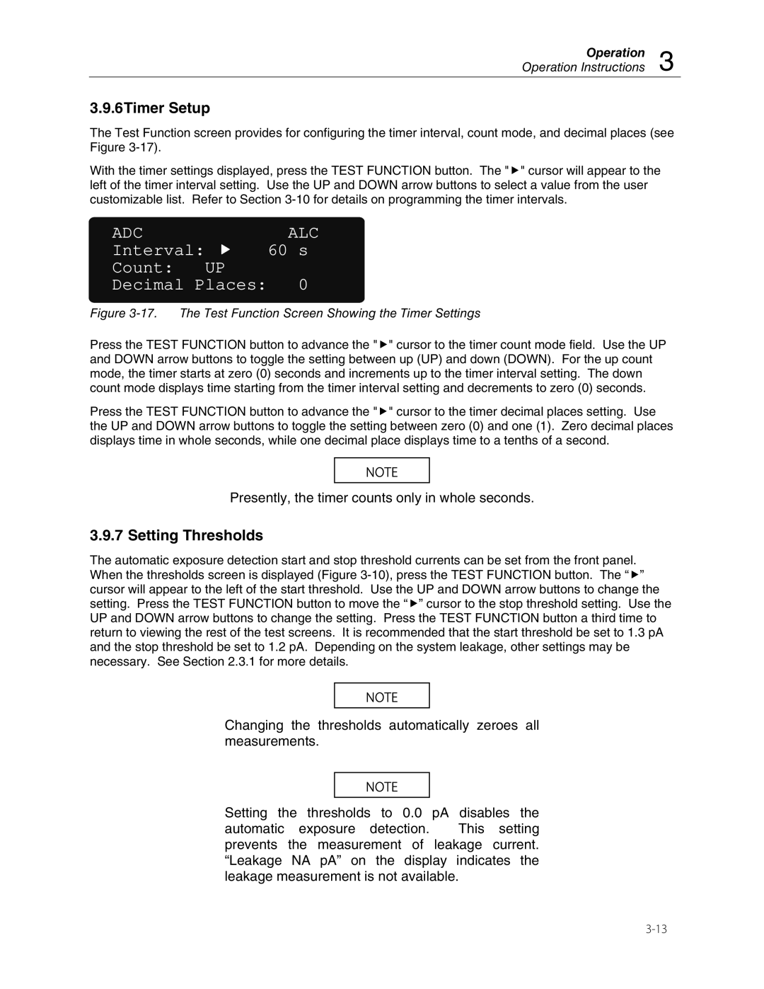
The Test Function screen provides for configuring the timer interval, count mode, and decimal places (see Figure
With the timer settings displayed, press the TEST FUNCTION button. The "f" cursor will appear to the left of the timer interval setting. Use the UP and DOWN arrow buttons to select a value from the user customizable list. Refer to Section
ADC | ALC |
Interval: | 60 s |
Count: UP | 0 |
Decimal Places: |
Figure 3-17. The Test Function Screen Showing the Timer Settings
Press the TEST FUNCTION button to advance the "f" cursor to the timer count mode field. Use the UP and DOWN arrow buttons to toggle the setting between up (UP) and down (DOWN). For the up count mode, the timer starts at zero (0) seconds and increments up to the timer interval setting. The down count mode displays time starting from the timer interval setting and decrements to zero (0) seconds.
Press the TEST FUNCTION button to advance the "f" cursor to the timer decimal places setting. Use the UP and DOWN arrow buttons to toggle the setting between zero (0) and one (1). Zero decimal places displays time in whole seconds, while one decimal place displays time to a tenths of a second.
NOTE
Presently, the timer counts only in whole seconds.
3.9.7 Setting Thresholds
The automatic exposure detection start and stop threshold currents can be set from the front panel. When the thresholds screen is displayed (Figure
NOTE
Changing the thresholds automatically zeroes all measurements.
NOTE
Setting the thresholds to 0.0 pA disables the
automatic exposure detection. This setting prevents the measurement of leakage current. “Leakage NA pA” on the display indicates the leakage measurement is not available.