Operation
Operation Instructions 3
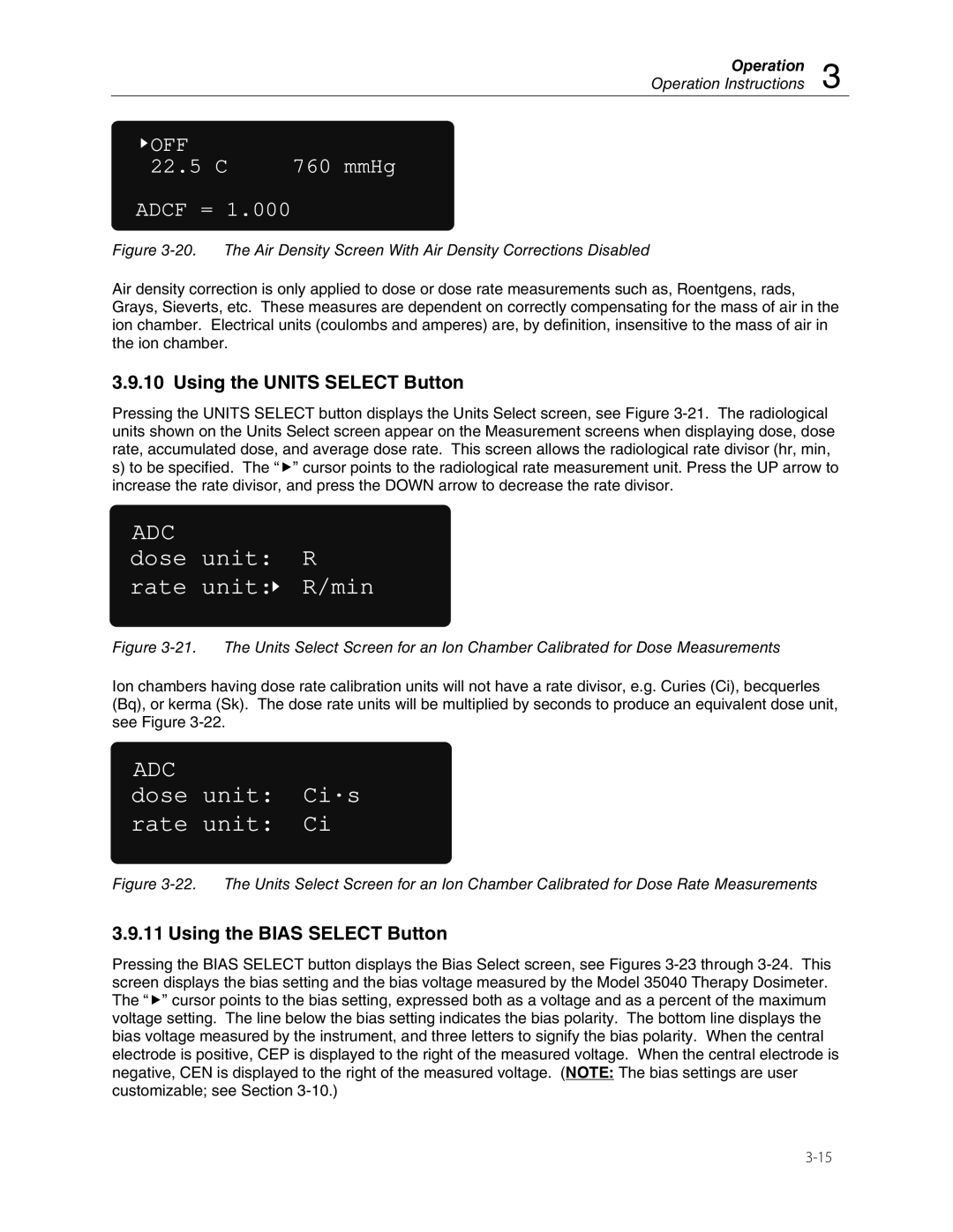
![]() OFF
OFF
22.5C 760 mmHg ADCF = 1.000
Figure 3-20. The Air Density Screen With Air Density Corrections Disabled
Air density correction is only applied to dose or dose rate measurements such as, Roentgens, rads, Grays, Sieverts, etc. These measures are dependent on correctly compensating for the mass of air in the ion chamber. Electrical units (coulombs and amperes) are, by definition, insensitive to the mass of air in the ion chamber.
3.9.10 Using the UNITS SELECT Button
Pressing the UNITS SELECT button displays the Units Select screen, see Figure
s)to be specified. The “f” cursor points to the radiological rate measurement unit. Press the UP arrow to increase the rate divisor, and press the DOWN arrow to decrease the rate divisor.
ADC
dose unit: R
rate unit: R/min
R/min
Figure 3-21. The Units Select Screen for an Ion Chamber Calibrated for Dose Measurements
Ion chambers having dose rate calibration units will not have a rate divisor, e.g. Curies (Ci), becquerles (Bq), or kerma (Sk). The dose rate units will be multiplied by seconds to produce an equivalent dose unit, see Figure
ADC
dose unit: Ci·s
rate unit: Ci
Figure 3-22. The Units Select Screen for an Ion Chamber Calibrated for Dose Rate Measurements
3.9.11 Using the BIAS SELECT Button
Pressing the BIAS SELECT button displays the Bias Select screen, see Figures