CHAPTER 1 OUTLINE AND CONFIGURATION EXAMPLE OF
1.2Configuration Example of Device Using F2MC-8FX CPU
The CPU, ROM, RAM and various resources for each
■Configuration Example of Device Using
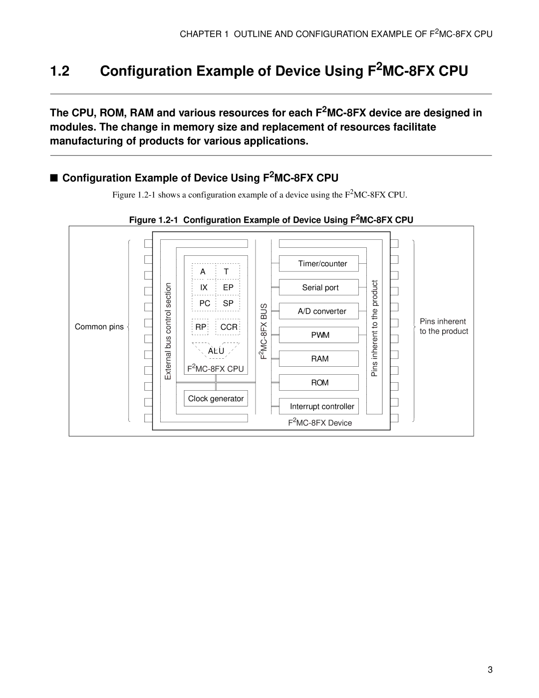
Figure 1.2-1 shows a configuration example of a device using the F2MC-8FX CPU.
Figure 1.2-1 Configuration Example of Device Using F2MC-8FX CPU
Common pins ![]()
| A | T |
|
control section | IX | EP |
|
PC | SP | 8FX BUS | |
RP | CCR | ||
|
| ||
bus | ALU | MC- | |
2 | |||
External |
| F | |
|
| ||
| Clock generator |
| |
Timer/counter
Serial port
A/D converter
PWM
RAM
ROM
Interrupt controller
Pins inherent to the product
Pins inherent to the product
3