APPENDIX
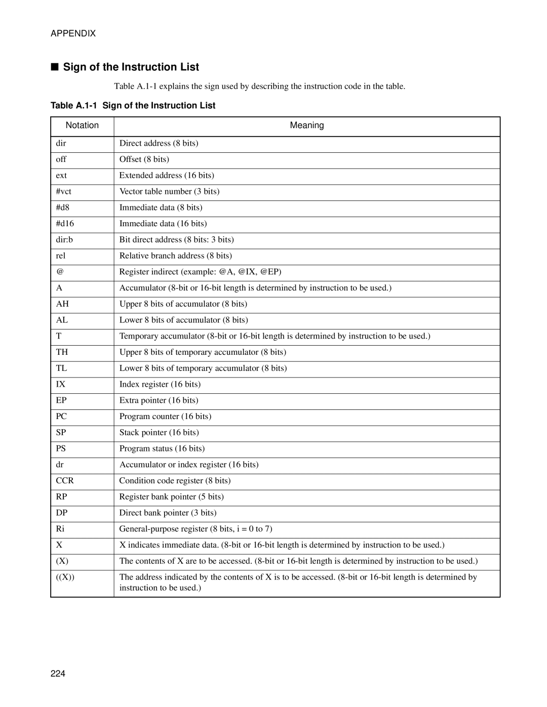
■Sign of the Instruction List
|
| Table |
Table | Sign of the Instruction List | |
|
|
|
Notation |
| Meaning |
|
|
|
dir |
| Direct address (8 bits) |
|
|
|
off |
| Offset (8 bits) |
|
|
|
ext |
| Extended address (16 bits) |
|
|
|
#vct |
| Vector table number (3 bits) |
|
|
|
#d8 |
| Immediate data (8 bits) |
|
|
|
#d16 |
| Immediate data (16 bits) |
|
|
|
dir:b |
| Bit direct address (8 bits: 3 bits) |
|
|
|
rel |
| Relative branch address (8 bits) |
|
|
|
@ |
| Register indirect (example: @A, @IX, @EP) |
|
|
|
A |
| Accumulator |
|
|
|
AH |
| Upper 8 bits of accumulator (8 bits) |
|
|
|
AL |
| Lower 8 bits of accumulator (8 bits) |
|
|
|
T |
| Temporary accumulator |
|
|
|
TH |
| Upper 8 bits of temporary accumulator (8 bits) |
|
|
|
TL |
| Lower 8 bits of temporary accumulator (8 bits) |
|
|
|
IX |
| Index register (16 bits) |
|
|
|
EP |
| Extra pointer (16 bits) |
|
|
|
PC |
| Program counter (16 bits) |
|
|
|
SP |
| Stack pointer (16 bits) |
|
|
|
PS |
| Program status (16 bits) |
|
|
|
dr |
| Accumulator or index register (16 bits) |
|
|
|
CCR |
| Condition code register (8 bits) |
|
|
|
RP |
| Register bank pointer (5 bits) |
|
|
|
DP |
| Direct bank pointer (3 bits) |
|
|
|
Ri |
| |
|
|
|
X |
| X indicates immediate data. |
|
|
|
(X) |
| The contents of X are to be accessed. |
|
|
|
((X)) |
| The address indicated by the contents of X is to be accessed. |
|
| instruction to be used.) |
|
|
|
224