CHAPTER 4 INTERRUPT PROCESSING
4.4Multiple Interrupt
The
■Multiple Interrupt
A specific example is given below.
•When giving priority over the A/D converter to the timer interrupt
START MOV | ADIL, | #2 | Set the interrupt level of the A/D converter to 2. |
MOV | TMIL, | #1 | Set the interrupt level of the timer to 1. ADIL and |
|
|
| TMIL are IL bits in the interrupt controller. |
CALL | STAD |
| Start the A/D converter. |
CALL | STTM |
| Start the timer. |
. |
|
|
|
. |
|
|
|
. |
|
|
|
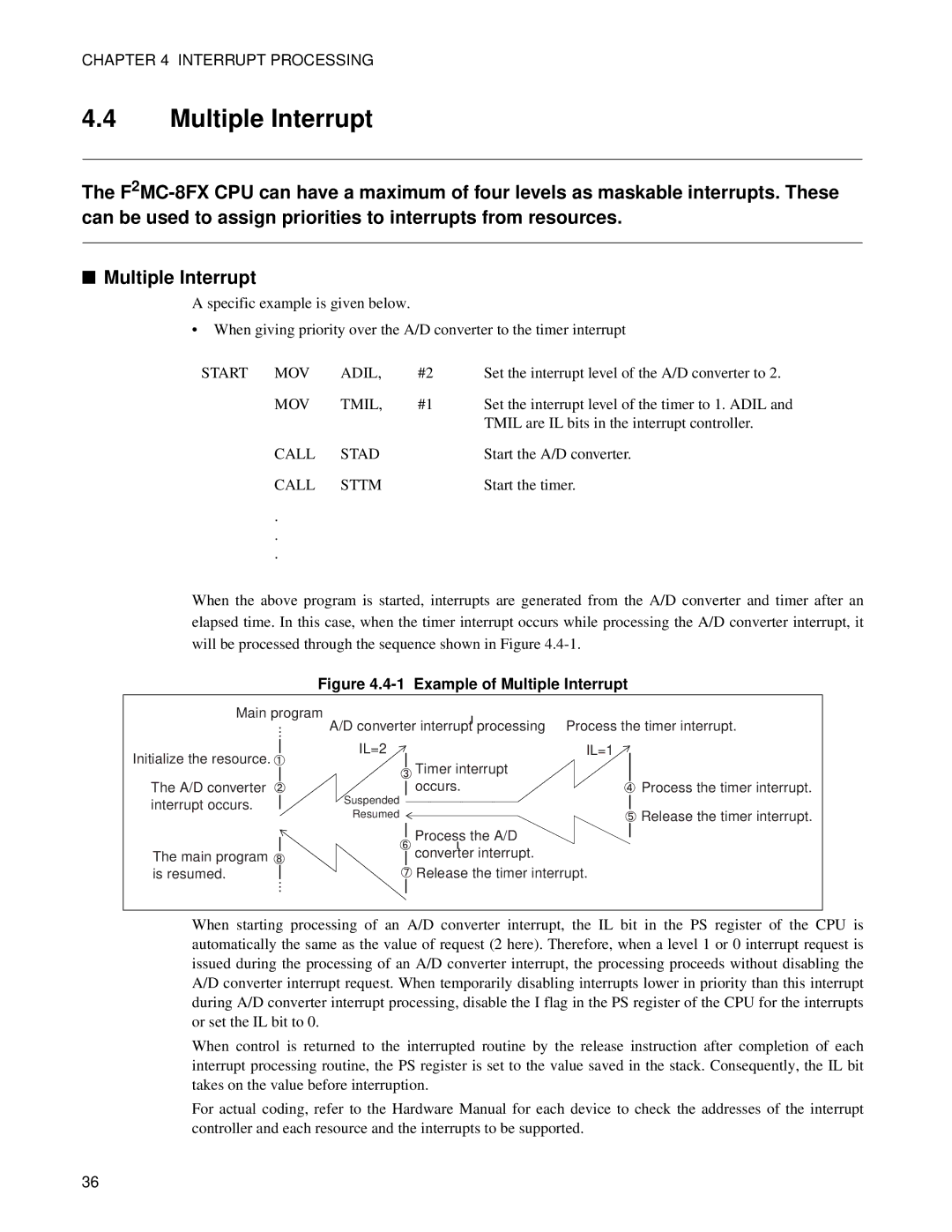
When the above program is started, interrupts are generated from the A/D converter and timer after an elapsed time. In this case, when the timer interrupt occurs while processing the A/D converter interrupt, it will be processed through the sequence shown in Figure
Figure 4.4-1 Example of Multiple Interrupt
Main program | A/D converter interruptı processing Process the timer interrupt. |
... |
Initialize the resource. ![]()
The A/D converter interrupt occurs.
The main program ![]() is resumed.
is resumed.
...
IL=2 | IL=1 |
![]() Timer interrupt occurs.
Timer interrupt occurs.
Suspended
Resumed
Process the A/D
ı
converter interrupt.
![]() Release the timer interrupt.
Release the timer interrupt.
![]() Process the timer interrupt.
Process the timer interrupt.
![]() Release the timer interrupt.
Release the timer interrupt.
When starting processing of an A/D converter interrupt, the IL bit in the PS register of the CPU is automatically the same as the value of request (2 here). Therefore, when a level 1 or 0 interrupt request is issued during the processing of an A/D converter interrupt, the processing proceeds without disabling the A/D converter interrupt request. When temporarily disabling interrupts lower in priority than this interrupt during A/D converter interrupt processing, disable the I flag in the PS register of the CPU for the interrupts or set the IL bit to 0.
When control is returned to the interrupted routine by the release instruction after completion of each interrupt processing routine, the PS register is set to the value saved in the stack. Consequently, the IL bit takes on the value before interruption.
For actual coding, refer to the Hardware Manual for each device to check the addresses of the interrupt controller and each resource and the interrupts to be supported.
36