MAP3367, MAP3735, MAP3147 NP/NC Series
For Safe Operation
Revision History
This page is intentionally left blank
Preface
Glossary
Preface
Conventions Used in this Manual
Scsi Ansi
Ansi
Manual Organization
This page is intentionally left blank
Contents
Contents
Contents
Contents
Sense Data Error Recovery Methods
Disk Media Management
Glossary GL-1 Abbreviations AB-1 Index IN-1
Illustrations
Tables
This page is intentionally left blank
LUN
Command Format
10-Byte CDB Basic Format
Command Processing
Command Format
Command Processing
Command Format
Status Byte Code
Status Byte
Outline of Command Processing Single commands
Command link
Outline of Command Processing
Reservation
Responses to Link Specification Commands
Conditions for Permitting a Disconnect
Disconnect/reconnect processing
Performed in the execution sequence
Types of Command and Disconnect Processing
Outline of Command Processing
Command Processing
Synchronous mode data transfer/wide mode data transfer
Untagged queuing
Command Queuing Function
If disconnect processing is impossible
If the IDD is reserved
Tagged queuing
Unit Attention Condition
READ, Read EXTENDED, WRITE, Write Extended
Generation of the Unit Attention condition
Command Processing
Target Reset
Unit Attention condition multiple hold
Sense Data Hold State Sense data hold condition
Response and release conditions at sense data hold state
Command Processing Exceptions Overlapping commands
Command Processing Exceptions
Illegal LUN specification
Command processing in the not ready state
Reserved operation code
Hardware Error
Sense data in not ready state
Not Ready
Error recovery processing
Outline of disk drive error recovery processing
Outline of Scsi Bus Error Recovery Processing
Reset processing
Fatal hardware errors
Reset processing during write
Data Block Addressing Definition of data space
Data Block Addressing
Data space configuration
Logical block addressing
Data Buffer Data buffer configuration and basic operation
Data Buffer Look-Ahead Cache Feature Write Cache
Init
Data Buffer Management
Example of data buffer operation during read
Data Buffer
Example of data buffer operation during write
Parameters for controlling reconnection timing
Operation mode setting
Caching operation
Look-Ahead Cache Feature
Read Read Extended
Write Write and Verify Write Extended
Read Write Extended Read Extended Write and Verify
Remark
Caching parameters
Look-Ahead operation, Look-Ahead volume
Write Cache
This page is intentionally left blank
Control/Sense Commands Test Unit Ready
Command Specifications
Command Specifications
Inquiry
Evpd
Control/Sense Commands
Standard Inquiry data
Control/Sense Commands
Command Specifications
Ackbreqb ACKB/REQB
Code Description
Byte
SAM2
OXS01, OX9B
Command support data
Command Specifications
VPD information VPD identifier list
Wdtr Untain Sdtr Rsrty Phscrc AGD ACE RTD
VPD information operation mode
PMI
Read Capacity
Change Definition
Read Capacity data
SCSI-3
SCSI-2
Sdtr Rsrty Phscrc AGD ACE RTD
Wdtr
Control/Sense Commands
Command Specifications
Mode Select
Command Specifications
Mode Select parameter structure
Block Descriptor
Header
Descriptor
Mode Select command Group 0 parameter configuration
Command Specifications
Control/Sense Commands
LSB
Mode Select Extended
Header
LUN DBD
CCS SCSI-2 SCSI-3
Mode Sense Data Type Specifications
Dpofua
10 Mode Sense command Group 0 parameter configuration
Command Specifications
Control/Sense Commands
Mode Sense Extended 5A
~ ~
START/STOP Unit 1B
Reserve
Command Specifications
Targ TARG/INIT
Reserve right and the third party reserve function Remark
Reserve Extended
Release
Request Sense
Release Extended
Control/Sense Commands
LUN PCR
LOG Select 4C
Reserved
TSD ETC TMC Lbin
Control/Sense Commands
LUN PPC
LOG Sense 4D
Persistent Reserve in 5E
Control/Sense Commands
Persistent Reserve in service actions
Read Keys
Read Keys
Persistent Reserve in parameter data for Read Keys
Read Reservations
MSB
LSB MSB
Persistent Reserve in parameter data for Read Reservations
Persistent reservation scope
Logical Unit scope
Element scope not supported by MA*3*** series product
Persistent reservations type
Persistent reservation type codes
Persistent Reserve OUT 5E
Persistent Reserve OUT service actions
Persistent Reserve OUT parameter list
Persistent Reserve OUT command service action codes
Control/Sense Commands
Ignore Existing
Persistent Reserve OUT service actions and valid parameters
KEY Reserve
Report Luns A0
LUN List Length N-7 Header
Report Device Identifier A3
SET Device Identifier A4
Command Specifications
Data Access Commands Read
Data Access Commands
LUN FUA
Read Extended
Write 0A
Write Extended 2A
Write and Verify 2E
Verify 2F
Seek Extended 2B
Seek 0B
SET Limits 33 Not Supported
Data Access Commands
Synchronize Cache
Format Commands Format Unit
Format Commands
Command Specifications
Format Commands
Defect List D List
FOV Dprv Dcrt Stpf
Dcrt disable certification Default value
Dpry disable primary Default value
Stpf stop format Default value
FOV format option valid
Immed Immediate
Defect list length
Byte distance from the index format defect descriptor
Format Commands
15 Defect descriptor physical sector address format
FOV Dpry
Format Unit command defect processing 1
Format Unit command defect processing 2
Reassign Blocks
Format Unit command defect processing 3
16 Reassign Block command defect data list configuration
= Hardware Error
Read Defect Data
17 Read Defect Data command Defect data configuration
Command Specifications
Format Commands
SELF-TEST Code
Send Diagnostic 1D
Error recovery control flags during the self-diagnosis test
Maintenance, Diagnostic Commands
Setting prohibited
PER DTE
Remark
Parameter
Parameter length
19 Send Diagnostic parameters page code list
Maintenance, Diagnostic Commands
Receive Diagnostic Results 1C
Maintenance, Diagnostic Commands
22 Receive Diagnostic Results response data page code list
Bit Byte ‘40’ Code ‘00’ Parameter Length ‘0A’
Write Buffer 3B
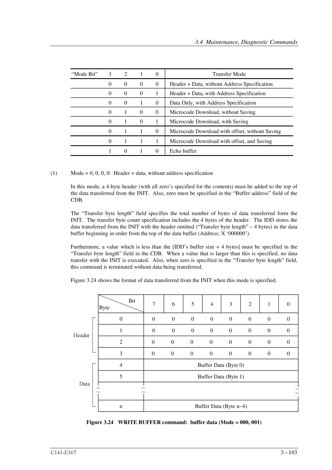
24 Write Buffer command buffer data Mode = 000
Command Specifications
Maintenance, Diagnostic Commands
Command Specifications
Read Buffer 3C
25 Read Buffer command buffer data Mode = 0000
26 Read Buffer command buffer descriptor
Ebos
27 Read Buffer command Echo buffer descriptor
05 = Illegal Request
Read Long 3E
Write Long 3F
Write Same
Command Specifications
Mode Parameters Log Parameters
Mode Parameters
Read/Write error recovery parameters page code =
Awre Arre ERR PER DTE DCR
Parameter Data Formats
‘FF’
‘FFFF’
Read Long Write Extended
Read Write Read Extended
Parameter Data Formats
Mode Parameters
Parameter Data Formats
EER PER DTE DCR
Combinations of error recovery flags 1
Combinations of error recovery flags 2
Combinations of error recovery flags 3
Disconnect/reconnect parameters page code =
Emdp Fair Arbitration
Dtdc
Mode Parameters
Parameter Data Formats
Mode Parameters
Format parameter page code =
Mode Select parameters format parameters
Mode Parameters
Parameter Data Formats
Drive parameter page code =
Mode Select parameters drive parameters
Verify error recovery parameters page code =
EER PER DTE DCR
Mode Select parameters verify error recovery parameters
Caching parameters page code =
Mode Select parameters caching parameters
Mode Parameters
Parameter Data Formats
Mode Parameters
Parameter Data Formats
TST
Control mode parameters page code = 0A
Gltsd Rlec
RAC
Parameter Data Formats
Mode Parameters
Parameter Data Formats
Notch parameter page code = 0C
Parameter Data Formats
Informational exceptions control page page code = 1C
EBF Ewasc
Mrie
Parameter Data Formats
Mrie
Additional error recovery parameters page code =
Value of Timer Interval field Actual time interval minutes
RPR
RFJ
Log Parameters
Supprot log
Buffer overrun / underrun
Write errors recovered without delays Page 02, Code
Write error count
Total posted write errors Page 02, Code
Write errors recovered with possible delays Page 02, Code
Total posted recoverable write errors Page 02, Code
Total write bytes processed Page 02, Code
LSB TSD ETC TMC Lbin
Read error count
Total posted unrecoverable write errors Page 02, Code
Read errors recovered with possible delays Page 03, Code
Read errors recovered without delays Page 03, Code
Total posted recoverable read errors Page 03, Code
Total posted read errors Page 03, Code
Total read bytes processed Page 03, Code
Total posted unrecoverable read errors Page 03, Code
Verify errors recovered without delays Page 05, Code
Verify error count
Total posted verify errors Page 05, Code
Vefiry errors recovered with possible delays Page 05, Code
Total verify bytes processed Page 05, Code
Total posted recoverable verify errors Page 05, Code
Non-medium error count
Total posted unrecoverable verify errors Page 05, Code
Temperature Page 0D, Code
Temperature page X0D
Start-stop cycle counter page X0E
Reference temperature Page 0D, Code
Accounting date Page 0E, Code
Date of manufacture Page 0E, Code
Start-stop cycle counter Page 0E, Code
Specified cycle count over device lifetime Page 0E, Code
Application client page X0F
Self-test result parameter data Page 10, Code
Self-test result
Smart data
Smart status page X2F
This page is intentionally left blank
Sense data format
Sense Data
ILI
Sense Data Error Recovery Methods
Sksv
IDD Scsi ID
Sense Data
Sense key inherent information
Sksv MSB
Sense key
Sense and subsense codes 1
Sense and subsense codes 2
Sense and subsense codes 3
Sense and subsense codes 4
Initiator Detected
Sense and subsense codes 5
Init Error Recovery Methods Recommended
Termination status analysis and error recovery methods
Sense data additional information
Analysis of the termination status
Init Error Recovery Methods Recommended
Sense data error classification
Sense data analysis and error recovery methods
Sense data error classification 2
Sense Data Error Recovery Methods
Error recovery processing procedures 1
Error Recovery Processing Procedures 2
Error recovery processing procedures 3
Init Error Recovery Methods Recommended
Error recovery processing procedures 4
Error logging
Error recovery processing procedures 5
Error states and retry processing procedures
Auto alternate block allocation processing
Disk Drive Error Recovery Processing
Remark
Error recovery processing control
EER
Disk drive errors and number of retries
Defect Management
Disk Media Management
Spare sectors within a cell
Disk Media Management
Alternate cells
Sector slip processing
Disk Media Initialization
Disk Media Initialization Initialization during installation
Disk Media Management
Re-initialization
Data Block Verification Methods Recommended
Alternate Block Allocation Processing
Disk Media Management
Glossary
Initiator Init
Glossary
Sense Key
This page is intentionally left blank
Acronyms and Abbreviations
This page is intentionally left blank
Fujitsu Canada INC
This page is intentionally left blank
Index
DCR Dcrt
Index
Format Unit
IDD Scsi ID
C141-E167 IN-5
RAC
Rezero Unit 3-35 RFJ
Untatn
Write and Verify 3-69, 4-20 Write Buffer
This page is intentionally left blank
NP/NC Series
Specifications
Series Disk Drives Scsi
Logical Interface
This page is intentionally left blank