Operations
6.2.2 Logical address
(1) CHS mode
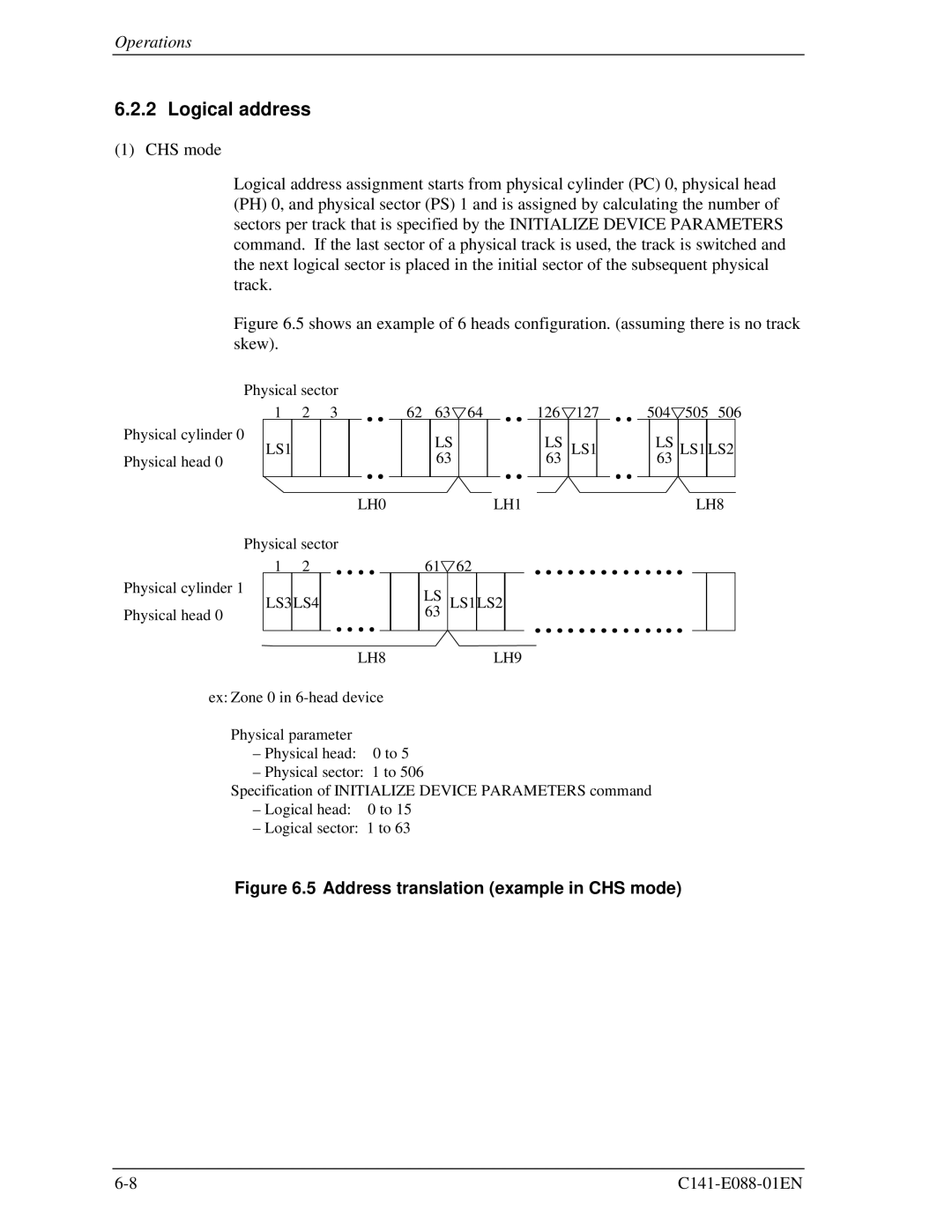
Logical address assignment starts from physical cylinder (PC) 0, physical head (PH) 0, and physical sector (PS) 1 and is assigned by calculating the number of sectors per track that is specified by the INITIALIZE DEVICE PARAMETERS command. If the last sector of a physical track is used, the track is switched and the next logical sector is placed in the initial sector of the subsequent physical track.
Figure 6.5 shows an example of 6 heads configuration. (assuming there is no track skew).
Physical sector
1 2 3
Physical cylinder 0
LS1
Physical head 0
LH0
Physical sector
62 | 63 | 64 |
|
| 126 | 127 |
| 504 | 505 | 506 | |||||
|
|
| |||||||||||||
|
| LS |
|
|
|
| LS | LS1 |
|
|
| LS | LS1 | LS2 |
|
|
|
|
|
|
|
|
|
|
| ||||||
|
| 63 |
|
|
|
| 63 |
|
|
|
| 63 |
|
|
|
|
|
|
|
|
|
|
|
|
|
|
|
|
|
|
|
|
|
|
|
|
|
|
|
|
|
|
|
|
| ||
|
|
|
| LH1 |
|
|
|
|
|
|
| LH8 | |||
1 | 2 |
|
|
| 61 | 62 |
|
| ||
|
|
|
|
| ||||||
Physical cylinder 1 | LS3LS4 |
|
|
|
| LS | LS1LS2 |
| ||
Physical head 0 |
|
|
|
|
| |||||
|
|
|
|
|
| 63 |
|
|
| |
|
|
|
|
|
|
|
|
|
|
|
|
|
|
|
|
|
|
|
|
| |
|
|
|
| LH8 |
|
|
| LH9 | ||
ex: Zone 0 in
Physical parameter
–Physical head: 0 to 5
–Physical sector: 1 to 506
Specification of INITIALIZE DEVICE PARAMETERS command
–Logical head: 0 to 15
–Logical sector: 1 to 63