Interface
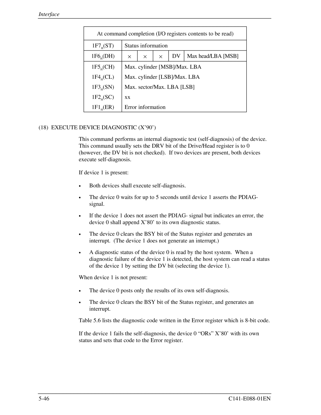
At command completion (I/O registers contents to be read)
1F7H(ST) | Status information |
|
| ||
|
|
|
|
|
|
1F6H(DH) | × | × | × | DV | Max head/LBA [MSB] |
|
|
|
|
|
|
1F5H(CH) | Max. cylinder [MSB]/Max. LBA | ||||
1F4H(CL) | Max. cylinder [LSB]/Max. LBA | ||||
1F3H(SN) | Max. sector/Max. LBA [LSB] | ||||
1F2H(SC) | xx |
|
|
|
|
1F1H(ER) | Error information |
|
| ||
(18) EXECUTE DEVICE DIAGNOSTIC (X’90’)
This command performs an internal diagnostic test
If device 1 is present:
∙
∙
∙
∙
∙
Both devices shall execute
The device 0 waits for up to 5 seconds until device 1 asserts the PDIAG- signal.
If the device 1 does not assert the PDIAG- signal but indicates an error, the device 0 shall append X’80’ to its own diagnostic status.
The device 0 clears the BSY bit of the Status register and generates an interrupt. (The device 1 does not generate an interrupt.)
A diagnostic status of the device 0 is read by the host system. When a diagnostic failure of the device 1 is detected, the host system can read a status of the device 1 by setting the DV bit (selecting the device 1).
When device 1 is not present:
∙
∙
The device 0 posts only the results of its own
The device 0 clears the BSY bit of the Status register, and generates an interrupt.
Table 5.6 lists the diagnostic code written in the Error register which is
If the device 1 fails the