Figure 1. Fiber Link Data Connections
DATA EQUIPMENT | FIBER LINK |
DATA OUT ![]() DATA IN
DATA IN
DATA IN ![]() DATA OUT
DATA OUT
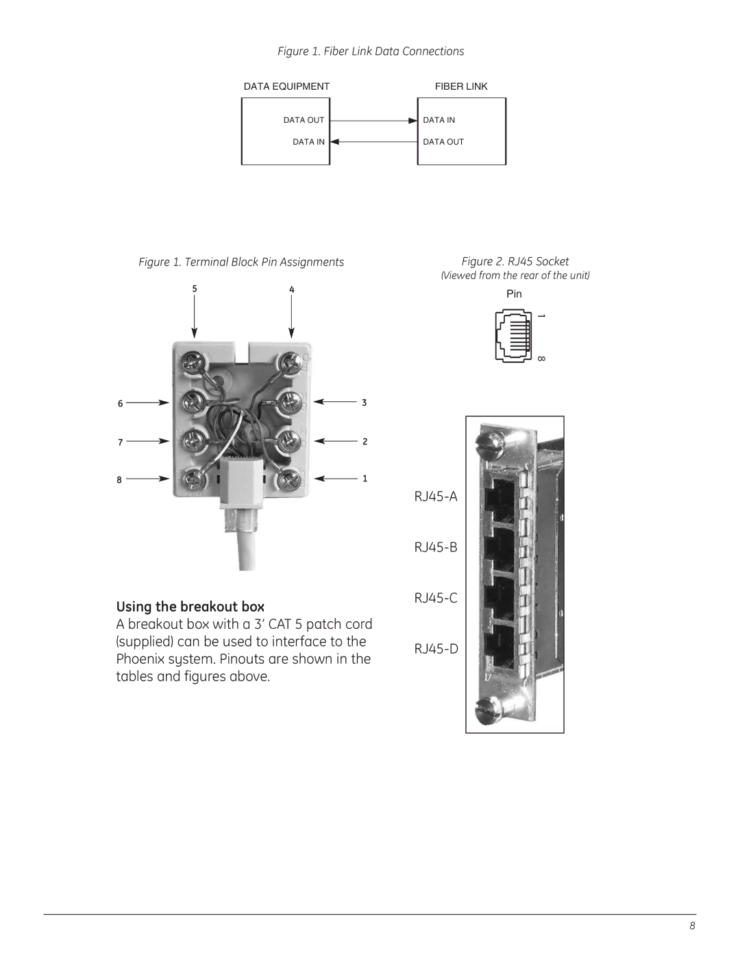
Figure 1. Terminal Block Pin Assignments
54
6 |
|
|
|
|
| 3 | ||
|
|
|
| |||||
7 |
|
|
|
| 2 | |||
|
| |||||||
8 |
|
|
|
| 1 | |||
|
| |||||||
Using the breakout box
A breakout box with a 3’ CAT 5 patch cord (supplied) can be used to interface to the Phoenix system. Pinouts are shown in the tables and figures above.
Figure 2. RJ45 Socket
(Viewed from the rear of the unit)
Pin
1 8
8