Main -> Local -> Data:
Data Menu
![]() 1. Input Mapping
1. Input Mapping
2.Output Mapping
3.Format Select
Data Input and Data Output channel mapping, monitoring, format and tests can be accessed from the
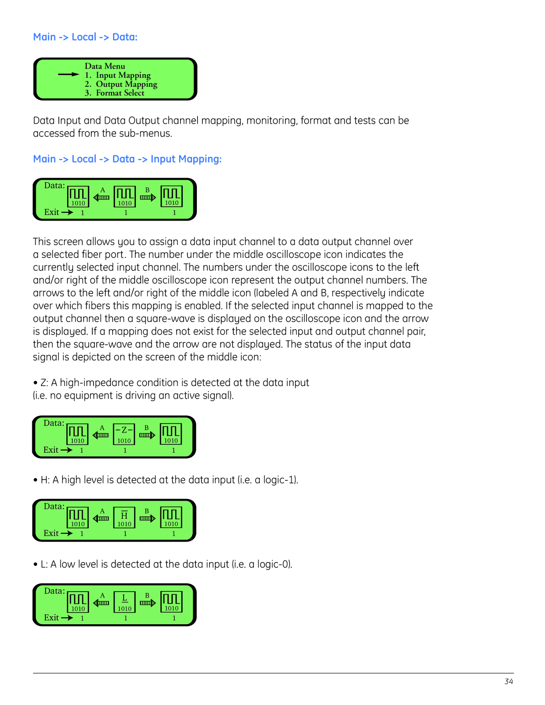
Main -> Local -> Data -> Input Mapping:
Data:
Exit
1010
1
A![]()
![]()
1010
1
B
1010
1
This screen allows you to assign a data input channel to a data output channel over a selected fiber port. The number under the middle oscilloscope icon indicates the currently selected input channel. The numbers under the oscilloscope icons to the left and/or right of the middle oscilloscope icon represent the output channel numbers. The arrows to the left and/or right of the middle icon (labeled A and B, respectively indicate over which fibers this mapping is enabled. If the selected input channel is mapped to the output channel then a
•Z: A
Data:
Exit
1010
1
A
Z
1010
1
B
1010
1
• H: A high level is detected at the data input (i.e. a
Data:
Exit
1010
1
A
H
1010
1
B
1010
1
• L: A low level is detected at the data input (i.e. a
Data:
Exit
1010
1
A
L
1010
1
B
1010
1
34