Getting Started
** CAUTION:
This product contains
Overview
Installing the Phoenix chassis is a
1.Install mounting hardware and power supplies.
2.Install modules and connect cabling.
3.Configure the system.
Determine Mounting Hardware
Mounting brackets are adjustable. Choose the best location to fit your application and position brackets using the supplied hardware. Remove screws holding front mounting bracket, move to top, bottom, back or front and refasten.
Installing Power Supplies
All installation should be from rear of rack unit.
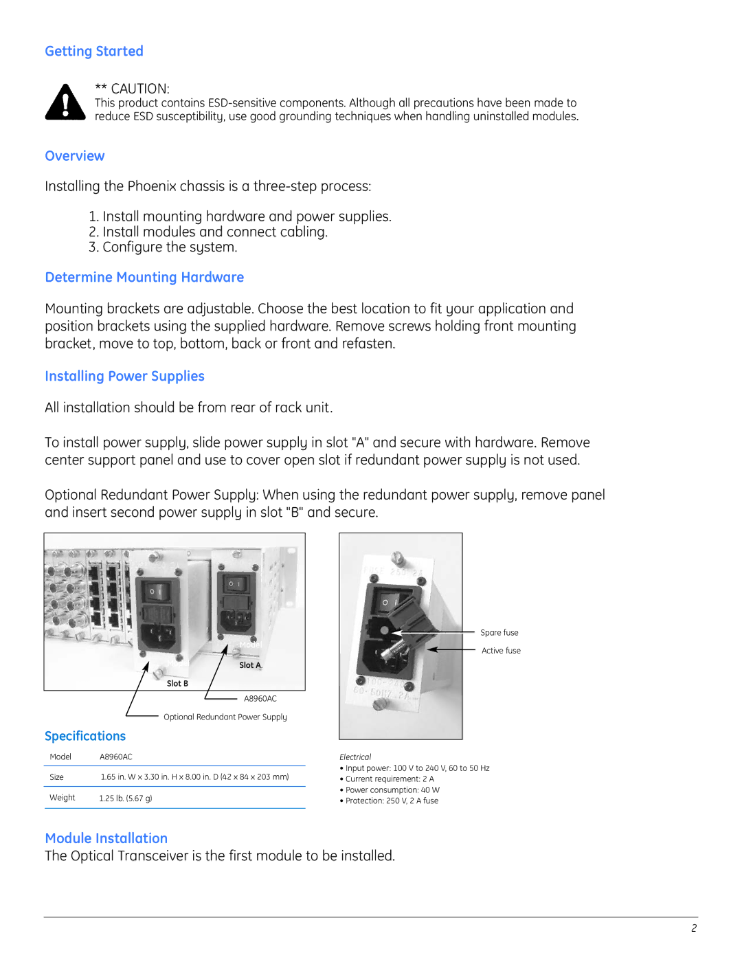
To install power supply, slide power supply in slot "A" and secure with hardware. Remove center support panel and use to cover open slot if redundant power supply is not used.
Optional Redundant Power Supply: When using the redundant power supply, remove panel and insert second power supply in slot "B" and secure.
| Model |
Model | Slot A. |
Slot B
A8960AC
Optional Redundant Power Supply
Specifications
| Model | A8960AC |
|
|
|
| Size | 1.65 in. W x 3.30 in. H x 8.00 in. D (42 x 84 x 203 mm) |
|
|
|
| Weight | 1.25 lb. (5.67 g) |
|
|
|
Spare fuse
Active fuse
Electrical
•Input power: 100 V to 240 V, 60 to 50 Hz
•Current requirement: 2 A
•Power consumption: 40 W
•Protection: 250 V, 2 A fuse
Module Installation
The Optical Transceiver is the first module to be installed.
2