2. Install data module:
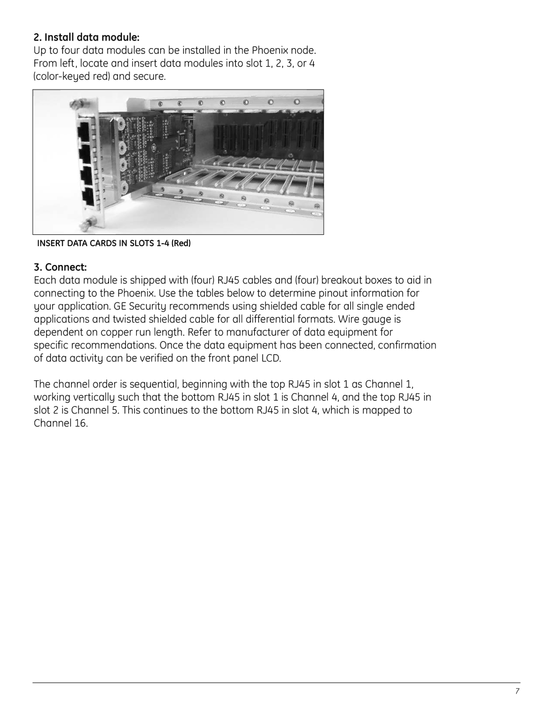
Up to four data modules can be installed in the Phoenix node. From left, locate and insert data modules into slot 1, 2, 3, or 4
INSERT DATA CARDS IN SLOTS
3. Connect:
Each data module is shipped with (four) RJ45 cables and (four) breakout boxes to aid in connecting to the Phoenix. Use the tables below to determine pinout information for your application. GE Security recommends using shielded cable for all single ended applications and twisted shielded cable for all differential formats. Wire gauge is dependent on copper run length. Refer to manufacturer of data equipment for specific recommendations. Once the data equipment has been connected, confirmation of data activity can be verified on the front panel LCD.
The channel order is sequential, beginning with the top RJ45 in slot 1 as Channel 1, working vertically such that the bottom RJ45 in slot 1 is Channel 4, and the top RJ45 in slot 2 is Channel 5. This continues to the bottom RJ45 in slot 4, which is mapped to Channel 16.
7