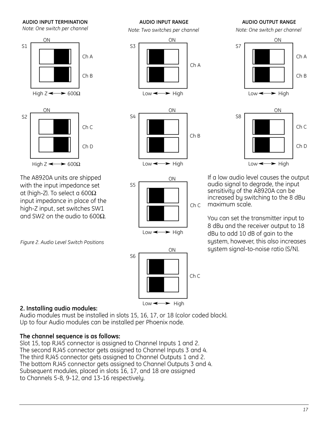
AUDIO INPUT TERMINATION Note: One switch per channel
ON
S1
Ch A
Ch B
High Z ![]()
![]() 600Ω
600Ω
ON
S2
Ch C
Ch D
|
| AUDIO INPUT RANGE | AUDIO OUTPUT RANGE | |||||||||||||||
Note: Two switches per channel | Note: One switch per channel | |||||||||||||||||
|
|
|
|
|
|
| ON | S7 |
|
|
|
|
| ON | ||||
S3 |
|
|
|
|
|
|
|
|
|
|
|
|
|
|
| Ch A | ||
|
|
|
|
|
|
|
|
|
|
|
|
|
|
|
|
|
| |
|
|
|
|
|
|
|
|
| Ch A |
|
|
|
|
|
|
|
| Ch B |
|
|
|
|
|
|
|
|
|
|
|
|
|
|
|
|
| ||
|
|
|
|
|
|
|
|
|
|
|
|
|
|
|
|
|
| |
|
|
|
|
|
|
|
|
|
|
|
|
|
|
|
|
|
|
|
|
|
|
|
|
|
|
|
|
|
|
|
|
|
|
|
|
|
|
|
| Low |
|
| High |
| Low |
|
| High | ||||||||
|
|
|
|
|
| |||||||||||||
S4 |
|
|
|
|
|
| ON | S8 |
|
|
|
|
| ON | ||||
|
|
|
|
|
|
|
|
|
|
|
| Ch C | ||||||
|
|
|
|
|
|
|
|
|
|
|
|
|
|
|
|
|
| |
|
|
|
|
|
|
|
|
| Ch B |
|
|
|
|
|
|
|
| Ch D |
|
|
|
|
|
|
|
|
|
|
|
|
|
|
|
|
| ||
|
|
|
|
|
|
|
|
|
|
|
|
|
|
|
|
|
| |
|
|
|
|
|
|
|
|
|
|
|
|
|
|
|
|
|
|
|
|
|
|
|
|
|
|
|
|
|
|
|
|
|
|
|
|
|
|
High Z |
| 600Ω |
|
The A8920A units are shipped with the input impedance set at
Figure 2. Audio Level Switch Positions
S5
S6
Low ![]()
![]() High
High
ON
Ch C
Low ![]()
![]() High
High
ON
Ch C
Low ![]()
![]() High
High
If a low audio level causes the output audio signal to degrade, the input sensitivity of the A8920A can be increased by switching to the 8 dBu maximum scale.
You can set the transmitter input to 8 dBu and the receiver output to 18 dBu to add 10 dB of gain to the system, however, this also increases system
Low ![]()
![]() High
High
2. Installing audio modules:
Audio modules must be installed in slots 15, 16, 17, or 18 (color coded black). Up to four Audio modules can be installed per Phoenix node.
The channel sequence is as follows:
Slot 15, top RJ45 connector is assigned to Channel Inputs 1 and 2. The second RJ45 connector gets assigned to Channel Inputs 3 and 4. The third RJ45 connector gets assigned to Channel Outputs 1 and 2. The bottom RJ45 connector gets assigned to Channel Outputs 3 and 4. Subsequent modules, placed in slots 16, 17, and 18 are assigned
to Channels
17