The third line, "2. Type" allows system events to be mapped to contact closure output channels:
•Transmitted. The contact behaves normally.
•Optic A: A problem on optic port A closes the selected contact.
•Optic B: A problem on optic port B closes the selected contact.
•Optic A or B: A problem on either optic port closes the selected contact.
•Video X: Loss of video on the specified video input channel
(where X is the video channel) closes the selected contact.
•Video W,X,Y,Z: Loss of video on any of the specified video input channels (where W,X,Y,Z are the video channels) closes the selected contact.
The fourth line, "3. Force" allows a contact output to be forced into a known state for test:
•None: The test is disabled and the contact behaves normally.
•Open: The contact is forced open.
•Closed: The contact is forced closed.
When leaving this menu with test patterns enabled, a warning message comes up alerting that the test states have been disabled to allow real contact closure information to pass.
Main -> Local -> Power:
Power Supply: A B Pass
+5V 5.2
+12V
11.9
This menu displays the measured voltages of the selected power supply. It also indicates the status of the power supply (Pass/ Fail). Use "+" to select the next power supply. Use "- " to select the previous power supply. Press "left" to exit this menu.
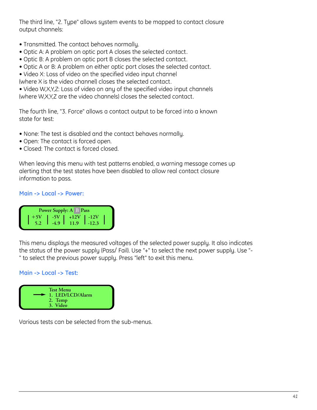
Main -> Local -> Test:
Test Menu
![]() 1. LED/LCD/Alarm
1. LED/LCD/Alarm
2.Temp
3.Video
Various tests can be selected from the
41