Dimension
3.3 Rear Panel
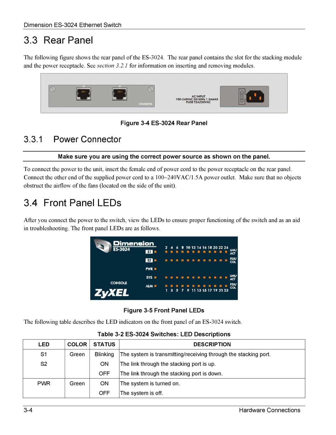
The following figure shows the rear panel of the
Figure 3-4 ES-3024 Rear Panel
3.3.1Power Connector
Make sure you are using the correct power source as shown on the panel.
To connect the power to the unit, insert the female end of power cord to the power receptacle on the rear panel. Connect the other end of the supplied power cord to a 100~240VAC/1.5A power outlet. Make sure that no objects obstruct the airflow of the fans (located on the side of the unit).
3.4 Front Panel LEDs
After you connect the power to the switch, view the LEDs to ensure proper functioning of the switch and as an aid in troubleshooting. The front panel LEDs are as follows.
|
|
| Figure |
The following table describes the LED indicators on the front panel of an | |||
|
| Table | |
|
|
|
|
LED | COLOR | STATUS | DESCRIPTION |
|
|
|
|
S1 | Green | Blinking | The system is transmitting/receiving through the stacking port. |
S2 |
| ON | The link through the stacking port is up. |
|
| OFF | The link through the stacking port is down. |
|
|
|
|
PWR | Green | ON | The system is turned on. |
|
| OFF | The system is off. |
|
|
|
|
Hardware Connections |