Dimension
| Table |
FIELD | DESCRIPTION |
|
|
Preset Value | Choose from Port Isolation, All Connected or Customized. |
| Port Isolation means that each port (1 to 26) can only communicate with the CPU management |
| port and cannot communicate with each other. All incoming ports are selected while only the CPU |
| outgoing port is selected. This option is the most limiting but also the most secure. |
| All Connected means all ports can communicate with each other, that is, there are no virtual |
| LANs. All incoming and outgoing ports are selected. This option is the most flexible but also the |
| least secure. |
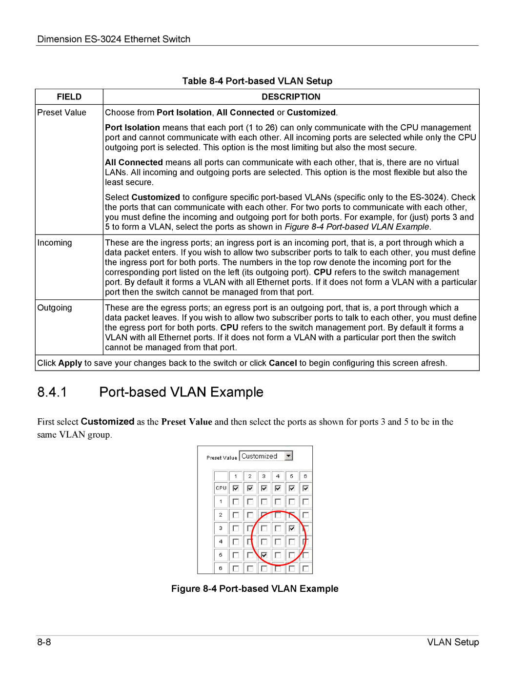
| Select Customized to configure specific |
| the ports that can communicate with each other. For two ports to communicate with each other, |
| you must define the incoming and outgoing port for both ports. For example, for (just) ports 3 and |
| 5 to form a VLAN, select the ports as shown in Figure |
Incoming | These are the ingress ports; an ingress port is an incoming port, that is, a port through which a |
| data packet enters. If you wish to allow two subscriber ports to talk to each other, you must define |
| the ingress port for both ports. The numbers in the top row denote the incoming port for the |
| corresponding port listed on the left (its outgoing port). CPU refers to the switch management |
| port. By default it forms a VLAN with all Ethernet ports. If it does not form a VLAN with a particular |
| port then the switch cannot be managed from that port. |
Outgoing | These are the egress ports; an egress port is an outgoing port, that is, a port through which a |
| data packet leaves. If you wish to allow two subscriber ports to talk to each other, you must define |
| the egress port for both ports. CPU refers to the switch management port. By default it forms a |
| VLAN with all Ethernet ports. If it does not form a VLAN with a particular port then the switch |
| cannot be managed from that port. |
Click Apply to save your changes back to the switch or click Cancel to begin configuring this screen afresh.
8.4.1Port-based VLAN Example
First select Customized as the Preset Value and then select the ports as shown for ports 3 and 5 to be in the same VLAN group.
Figure 8-4 Port-based VLAN Example
VLAN Setup |
