Dimension
Figure 3-2 Loosening the Screws and Removing the Cover Plate
Step 3. You should wear an
Step 4. Remove the optional module from its protective
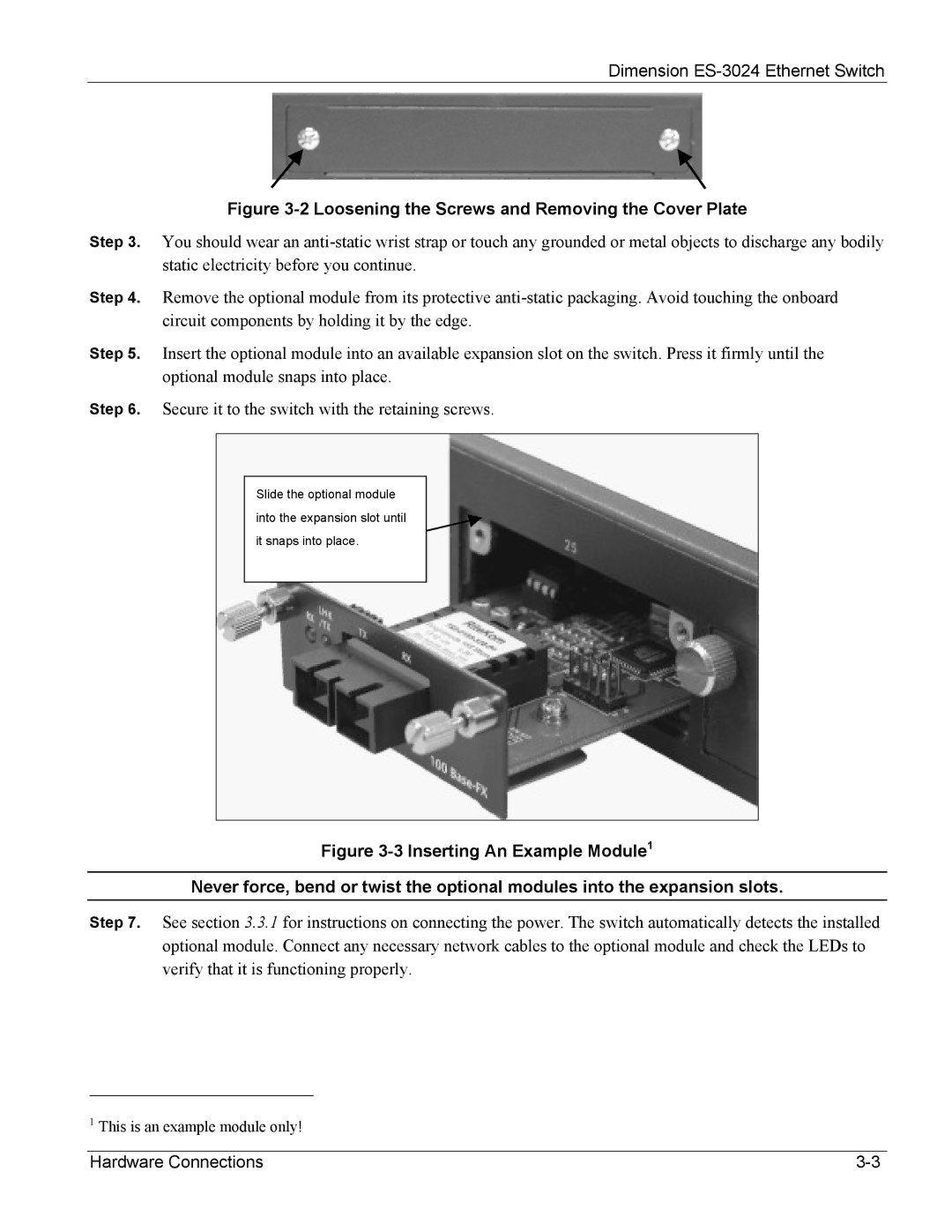
Step 5. Insert the optional module into an available expansion slot on the switch. Press it firmly until the optional module snaps into place.
Step 6. Secure it to the switch with the retaining screws.
Slide the optional module
into the expansion slot until
it snaps into place.
Figure 3-3 Inserting An Example Module1
Never force, bend or twist the optional modules into the expansion slots.
Step 7. See section 3.3.1 for instructions on connecting the power. The switch automatically detects the installed optional module. Connect any necessary network cables to the optional module and check the LEDs to verify that it is functioning properly.
1This is an example module only!
Hardware Connections |