Dimension
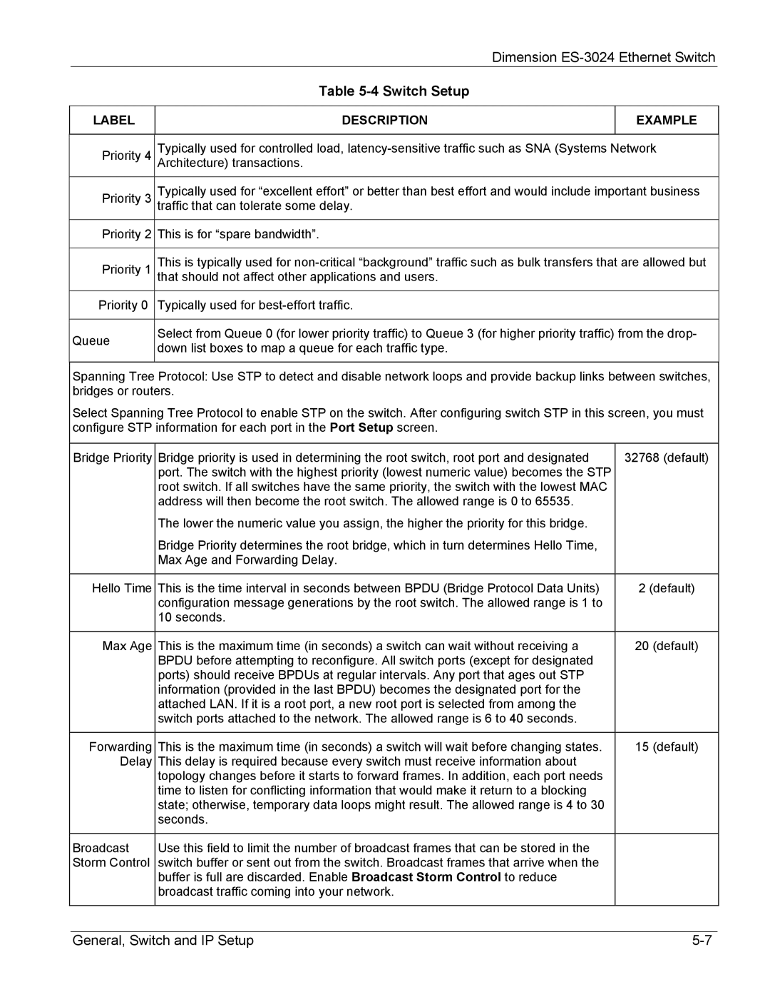
Table 5-4 Switch Setup
LABEL
DESCRIPTION
EXAMPLE
Priority 4 | Typically used for controlled load, | |
| Architecture) transactions. | |
Priority 3 | Typically used for “excellent effort” or better than best effort and would include important business | |
| traffic that can tolerate some delay. | |
Priority 2 | This is for “spare bandwidth”. | |
|
| |
Priority 1 | This is typically used for | |
| that should not affect other applications and users. | |
Priority 0 | Typically used for | |
|
| |
Queue | Select from Queue 0 (for lower priority traffic) to Queue 3 (for higher priority traffic) from the drop- | |
down list boxes to map a queue for each traffic type. | ||
| ||
|
|
Spanning Tree Protocol: Use STP to detect and disable network loops and provide backup links between switches, bridges or routers.
Select Spanning Tree Protocol to enable STP on the switch. After configuring switch STP in this screen, you must configure STP information for each port in the Port Setup screen.
Bridge Priority | Bridge priority is used in determining the root switch, root port and designated | 32768 (default) |
| port. The switch with the highest priority (lowest numeric value) becomes the STP |
|
| root switch. If all switches have the same priority, the switch with the lowest MAC |
|
| address will then become the root switch. The allowed range is 0 to 65535. |
|
| The lower the numeric value you assign, the higher the priority for this bridge. |
|
| Bridge Priority determines the root bridge, which in turn determines Hello Time, |
|
| Max Age and Forwarding Delay. |
|
|
|
|
Hello Time | This is the time interval in seconds between BPDU (Bridge Protocol Data Units) | 2 (default) |
| configuration message generations by the root switch. The allowed range is 1 to |
|
| 10 seconds. |
|
|
|
|
Max Age | This is the maximum time (in seconds) a switch can wait without receiving a | 20 (default) |
| BPDU before attempting to reconfigure. All switch ports (except for designated |
|
| ports) should receive BPDUs at regular intervals. Any port that ages out STP |
|
| information (provided in the last BPDU) becomes the designated port for the |
|
| attached LAN. If it is a root port, a new root port is selected from among the |
|
| switch ports attached to the network. The allowed range is 6 to 40 seconds. |
|
|
|
|
Forwarding | This is the maximum time (in seconds) a switch will wait before changing states. | 15 (default) |
Delay | This delay is required because every switch must receive information about |
|
| topology changes before it starts to forward frames. In addition, each port needs |
|
| time to listen for conflicting information that would make it return to a blocking |
|
| state; otherwise, temporary data loops might result. The allowed range is 4 to 30 |
|
| seconds. |
|
|
|
|
Broadcast | Use this field to limit the number of broadcast frames that can be stored in the |
|
Storm Control | switch buffer or sent out from the switch. Broadcast frames that arrive when the |
|
| buffer is full are discarded. Enable Broadcast Storm Control to reduce |
|
| broadcast traffic coming into your network. |
|
|
|
|
General, Switch and IP Setup |