Dimension
Chapter 3
Hardware Connections
This chapter acquaints you with the front and rear panels, shows you how to make the connections, install/remove (optional) modules and explains the LEDs.
3.1 Front Panel
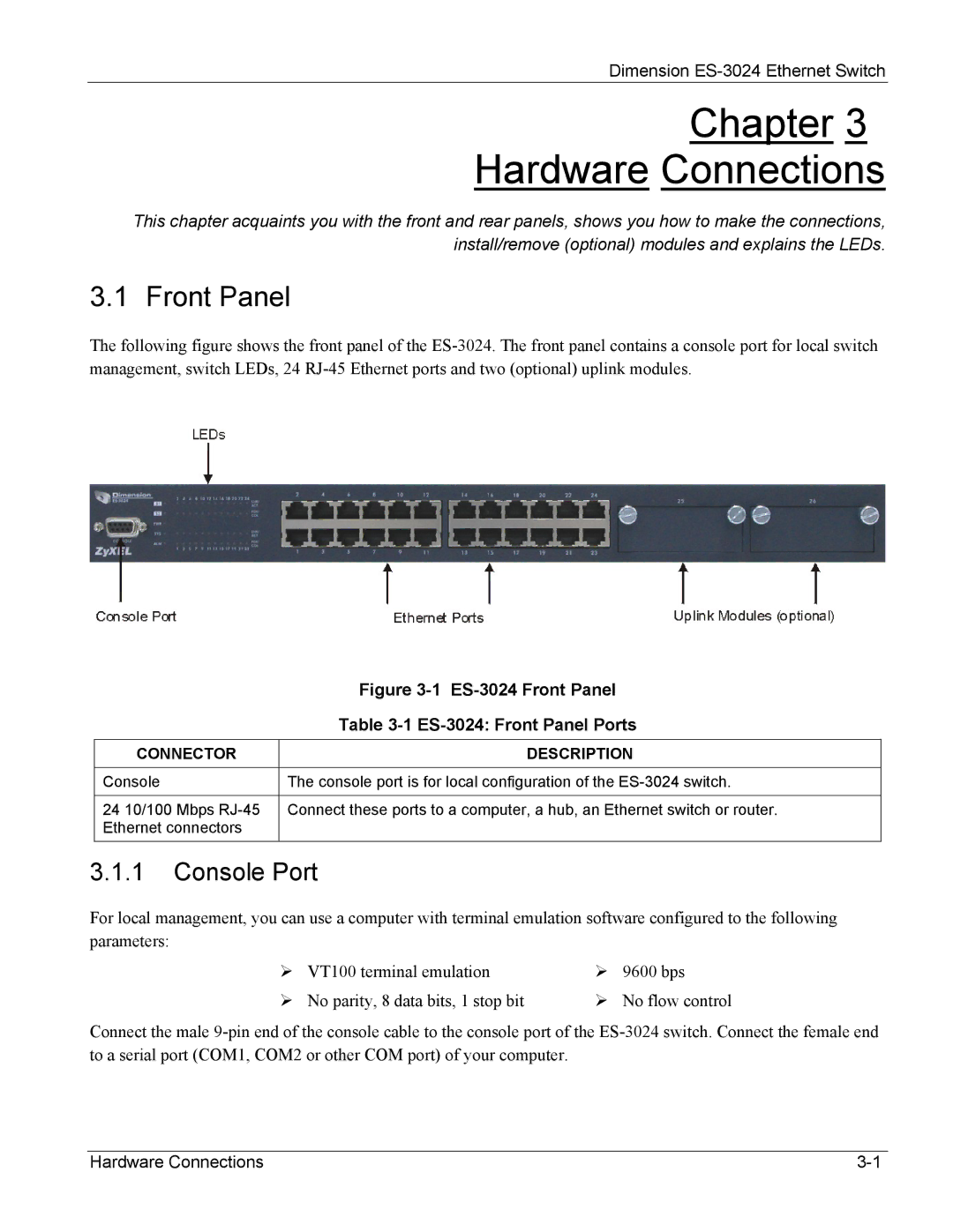
The following figure shows the front panel of the
| Figure |
| Table |
|
|
CONNECTOR | DESCRIPTION |
|
|
Console | The console port is for local configuration of the |
|
|
24 10/100 Mbps | Connect these ports to a computer, a hub, an Ethernet switch or router. |
Ethernet connectors |
|
|
|
3.1.1Console Port
For local management, you can use a computer with terminal emulation software configured to the following parameters:
VT100 terminal emulation | 9600 bps |
No parity, 8 data bits, 1 stop bit | No flow control |
Connect the male
Hardware Connections |
