|
|
| Dimension |
|
| Table | |
|
|
|
|
LED | COLOR | STATUS | DESCRIPTION |
|
|
|
|
SYS | Green | Blinking | The system is rebooting and performing |
|
| ON | The system is on and functioning properly. |
|
| OFF | The power is off or the system is not ready/malfunctioning. |
|
|
|
|
ALM | Red | ON | There is a hardware failure. |
|
| OFF | The system is functioning normally. |
|
|
|
|
LNK/ACT | Green | Blinking | The system is transmitting/receiving to/from a 10 Mbps Ethernet network. |
(Ethernet ports) |
| ON | The link to a 10 Mbps Ethernet network is up. |
|
| ||
|
| OFF | The link to a 10 Mbps Ethernet network is down. |
|
|
|
|
| Yellow | Blinking | The system is transmitting/receiving to/from a 100 Mbps Ethernet network. |
|
| ON | The link to a 100 Mbps Ethernet network is up. |
|
| OFF | The link to a 100 Mbps Ethernet network is down. |
|
|
|
|
FDX/COL | Yellow | Blinking | The Ethernet port is negotiating in |
(Ethernet ports) |
|
| occurring; the more collisions that occur the faster the LED blinks. |
|
| ON | The Ethernet port is negotiating in |
|
| OFF | The Ethernet port is negotiating in |
|
|
| occurring. |
3.5 Stacking Scenario Examples
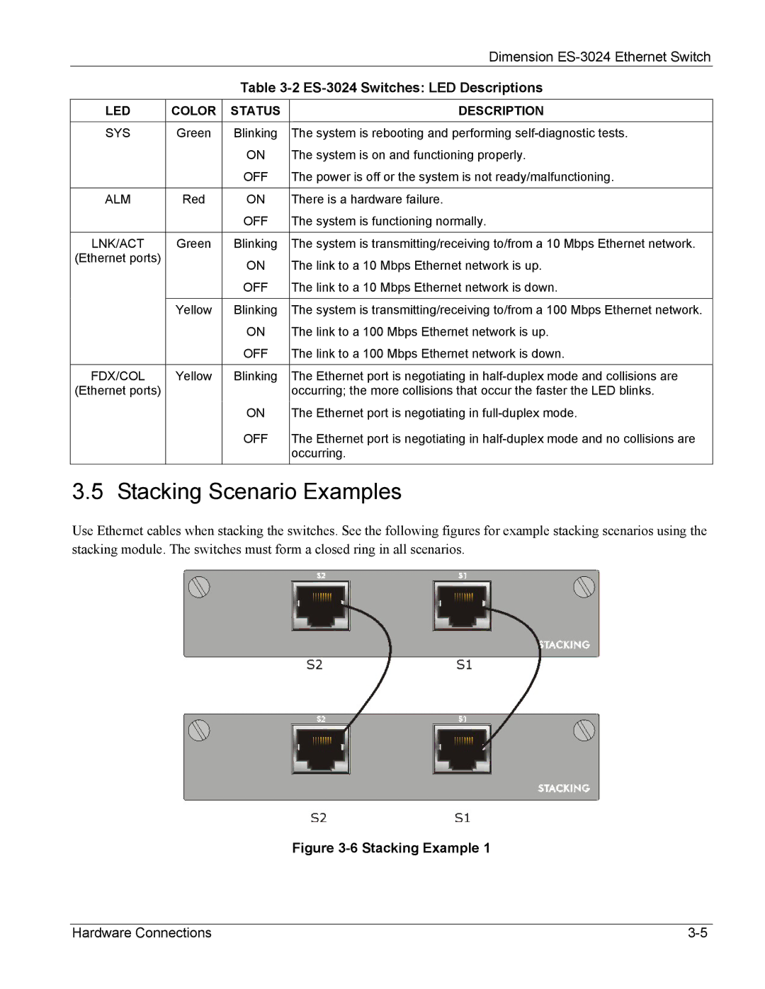
Use Ethernet cables when stacking the switches. See the following figures for example stacking scenarios using the stacking module. The switches must form a closed ring in all scenarios.
Figure 3-6 Stacking Example 1
Hardware Connections |
