Installing the Audio Module
Overview
The Phoenix A8920A audio module is capable of inputting and outputting up to 4 audio channels. The audio module occupies one audio slot (color coded black) and with up to four slots available, each node has a capacity of 16 channels. The audio interface connector is four, ganged RJ45 connectors located on each card. The audio module supports an audio test pattern, similar to GE Security standards.
Tools and materials required
The audio modules are held in place with simple thumbscrews with screwdriver slots. The only tool recommended is a small flat blade screwdriver.
Installation instructions:
1. Configure audio module:
Prior to installation, the audio modules need to be configured for proper
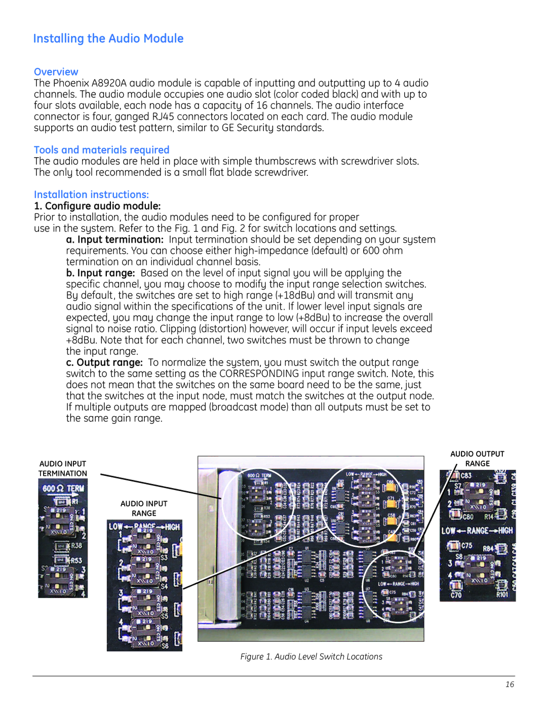
use in the system. Refer to the Fig. 1 and Fig. 2 for switch locations and settings.
a. Input termination: Input termination should be set depending on your system requirements. You can choose either
b. Input range: Based on the level of input signal you will be applying the specific channel, you may choose to modify the input range selection switches. By default, the switches are set to high range (+18dBu) and will transmit any audio signal within the specifications of the unit. If lower level input signals are expected, you may change the input range to low (+8dBu) to increase the overall signal to noise ratio. Clipping (distortion) however, will occur if input levels exceed +8dBu. Note that for each channel, two switches must be thrown to change the input range.
c. Output range: To normalize the system, you must switch the output range switch to the same setting as the CORRESPONDING input range switch. Note, this does not mean that the switches on the same board need to be the same, just that the switches at the input node, must match the switches at the output node. If multiple outputs are mapped (broadcast mode) than all outputs must be set to the same gain range.
AUDIO INPUT
TERMINATION
AUDIO INPUT
RANGE
AUDIO OUTPUT
RANGE
Figure 1. Audio Level Switch Locations
16